Table of Contents
Advertisement
Advertisement
Table of Contents

Subscribe to Our Youtube Channel
Summary of Contents for IEI Technology ACCURA9
- Page 1 ACCURA9/9L INSTRUCTION MANUAL Iwashita Engineering Inc. Ver.3.1 ’04/03/22...
-
Page 2: Table Of Contents
2 CONTENTS 1 General.........................3 2 Standard Specifications ..................4 3 Features of ACCURA9/9L ................5 Features ....................5 4 Component Names....................6 Front Panel of Controller..............6 Rear Panel of Controller..............7 5 Set up ........................8 6 9 Before using ACCURA 9/9L ..............7 Standard Operation ..................10... -
Page 3: General
Keep the unit away from vibration or shock from outside. Never let the noise in Accura9/9L controller and the wiring cable. Ground lead is required, or you may get an electoric shock. Never operate the unit according with any other instructions not stated in the instruction manual. -
Page 4: Standard Specifications
4 2 Standard Specifications Power Source .... AC85V~AC264V 50/60HZ Power Consumption .... 12VA in approx. Air Source Accura9 ....Shot-pressure applied ~ 735.5kPa Accura9L ....245.2~343.2kPa (Non-lubricated dry air and air-micron filter should be used.)... -
Page 5: Features Of Accura9/9L
Buzzer rings when the material reaches the set level. Pressure compensation for Line coating can be dispensed evenly and constantly by cartridge means of pressure compensation when using170cc cartridge Communications By RS232 Communication, ACCURA 9 can be controlled from external host computer. ACCURA9/9L INSTRUCTION MANUAL... -
Page 6: 4 Component Names
⑤ ... ⑬ ... Cursor key /OFF(shot) key ⑥ ... REMOTE key ⑭ ... CTRL key ⑦ ... MENU key ⑮ ... H key (←) (→) ⑧ ... Cursor key ⑯ ... Cursor key ④〜⑯ are key names. ACCURA9/9L INSTRUCTION MANUAL... -
Page 7: Rear Panel Of Controller
① ⑧ Components Names ① ... Air Import Port ② ... Exhaust silencer ③ ... Control connector ④ ... Outer input/output connector ⑤ ... Power source connector ⑥ ... Fuse ⑦ ... Ground ⑧ ... RS232C connector ACCURA9/9L INSTRUCTION MANUAL... -
Page 8: Set Up
70-80%. No bubble should be inside the barrel. Turn on the power switch on front panel. Wipe off the material stuck around 1-2cm from the upper side of the barrel, and then connect the adapter assembly with the barrel. Now start. ACCURA9/9L INSTRUCTION MANUAL... -
Page 9: Before Using Accura 9/9L
The system information and the unit of pressure are also *** Automatic ****** shown. Dispenser Press CTRL+CLR RESET key while the title-display. * * ACCURA9 Ver 3.0 * Or, press CTRL+CLR RESET key soon after turning on ** Sys01*kPa * ******** the switch. The system parameter is shown on the screen. -
Page 10: 7 Standard Operation
If there are multiple input items on the screen, the following procedures should be taken. 1) Go forward the item with MENU Key. 2) Return to the previous item with SHIFT+MENU Key. 3) Return to the initial item on the screen with H+MENU Key. ACCURA9/9L INSTRUCTION MANUAL... -
Page 11: Mode Selecting
Press CTRL+CLR RESET keys to clear the data for all channels. Messege Confirmation A confirmation message appears on the screen when DATA CLEAR? enter the key. Press Return key for ‘carry-on’, and press YES .. RETURN CLR Reset key for ‘cancel’. NO .. CLR RST ACCURA9/9L INSTRUCTION MANUAL... -
Page 12: Auto Mode
EMP ・・・Empty alarm function is working. DE ・・・Empty alarm function is working. (If ‘continue to dispense’ is selected.) Shot-pressure compensation for viscosity: Lapsed time・・・ Lapsed time after exchanging of barrels (hour and minute) on the upper left side of the screen. ACCURA9/9L INSTRUCTION MANUAL... - Page 13 Dispensing counter/Count-up Count Up Screen Count-up will appear on the screen and buzzer will ring when Sc ******************** SHOT COUNT (dispensing counter) reaches the initial setting. Reset with CLR COUNT UP!! RESET key. ******************** ACCURA9/9L INSTRUCTION MANUAL...
- Page 14 When only foot switch is used, it can be shifted to input through LCD panel by pressing SHIFT+REMOTE key. ※ Refer to 10 “Remote Mode” in the instruction manual for details. End AUTO mode To end AUTO mode, enter H+MODE keys except when REMOTE Mode. ACCURA9/9L INSTRUCTION MANUAL...
-
Page 15: Data Editing Screen
・ Input the size of barrel (5, 10, 30, 50 and 170 cc) by cursor keys Remark If the barrel size is input incorrectly, each compensation function and empty alarm may not work properly. ACCURA9/9L INSTRUCTION MANUAL... - Page 16 . SAVE DATA? *** DATA EDIT *** YES ..RETURN SAVING DATA! * ******************** NO .. CLR RST Remark When the shot-pressure, shot-period and/or barrel sizes are changed and saved, the setting sampling data for Bot-Level, Top-Level and Emp-Level become invalidly as NOD. ACCURA9/9L INSTRUCTION MANUAL...
- Page 17 3 digit from the left : Shot interval to increase the pressure.(Shot number) ( kPa: 000.0Kpa ) 3 digit from the right: Pressure increased value. ※ The above compensation functions cannot be used at the same time. AUTO mode end Input H+MODE key to end AUTO mode. ACCURA9/9L INSTRUCTION MANUAL...
- Page 18 OFF : Function set off NOD : No sampling data to be memorized. (※2) Except the level compensation, NOD is always shown no matter what the memorized data is. (※3) ON : Function set OFF : Function set off ACCURA9/9L INSTRUCTION MANUAL...
- Page 19 The sampling data for vacuum condition besides the level compensation should be downloaded into ROM at Top_Level. The vacuum condition is changeable. End the screen of AUTO MODE Press H+MODE key to end AUTO MODE. ACCURA9/9L INSTRUCTION MANUAL...
-
Page 20: D.samp Setting Screen
Level compensation VC ・・・ Vacuum compensation is working. EMP ・・・ Empty alarm is working. DE ・・・ Empty alarm function is detected while selecting “continue to shot.” (if ‘continue to dispense’ is selected. ) ACCURA9/9L INSTRUCTION MANUAL... - Page 21 ※ When using only foot switch, it is switchable from LCD panel by pressing SHIFT +REMOTE key ※ Refer to Art. 10. Remote Mode for the detail of remote mode. Completion of STEADY Mode Press the H+MODE key except when entering the remote mode to finish the STEADY Mode. ACCURA9/9L INSTRUCTION MANUAL...
-
Page 22: Data Editing Screen
Range of barrels : 5 cc, 10 cc, 30 cc, 50 cc and 170 cc. Remark : Each compensate function and empty alarm function may not be carried out unless the size of barrel is set correctly. ACCURA9/9L INSTRUCTION MANUAL... - Page 23 If the saving data is carried out after having changed the shot pressure, the minimum shot period and the size of barrel, the sampling data of Bot_Level & Top_Level and the setting of empty detection on Emp_Level become invalid ( NOD ). ACCURA9/9L INSTRUCTION MANUAL...
- Page 24 Enter D.SAMP at the STEADY mode as the same key operation as at AUTO mode. In this screen, set data sampling, vacuum compensation and empty detection of each channel Refer to the D.SAMP screen for further detail in AUTO mode. ACCURA9/9L INSTRUCTION MANUAL...
-
Page 25: Viscosity Mode
Save the data by RETURN key. Confirmation screen is shown when completed saving the data. RETURN key to save and CLR RESET key to stop. Completion of the VISCOSITY Mode Press the H+MODE key in order to finish the viscosity mode. ACCURA9/9L INSTRUCTION MANUAL... -
Page 26: Rs232C Communication Setting
Press H+Mode key to complete the RS232C Mode. Saving data Save data with Return key. When saving the data, the confirmation screen is shown. Press Return key to save the data, and press Clr Reset key to stop it. Error screen ACCURA9/9L INSTRUCTION MANUAL... - Page 27 This screen appears when there is difference between values of checksum transmitted in RS232C and of checksum caliculated inside of dispenser Check Sum Error Screen *** RS232C * CHECK SUM ERROR * ******************** 4. RS232C Status Error This screen appears when Parity, Over-run or Framing error occurs during communication.. Status Error Screen *** RS232C * STATUS ERROR * ******************** ACCURA9/9L INSTRUCTION MANUAL...
- Page 28 Transmit the command from the host computer to clear the alarm. Or press the CLR RESET key. In case of 4 and 5: Press the CLR RESET key. Command from the host computer to clear alarm is unnecessary. ACCURA9/9L INSTRUCTION MANUAL...
-
Page 29: Data Sampling
The dispensing for download of sampling data is Sampling Screen carried out a few times. *** Sampling Mode ** During the sampling, this screen appears. After the sampling, D. SAMP setting function will * DATA SAMPLING!! * appear. ******************** The procedure at the lower level of barrel is completed. ACCURA9/9L INSTRUCTION MANUAL... - Page 30 Put the cursor on the Emp_Level ‘OFF’ by setting Top̲Level ON (↑、↓) the cursor key unless using the empty Emp̲Level OFF alarm function. Press CTRL+RETURN key while putting the cursor key on Emp_Level if using the empty alarm function. The next screen will appear. ACCURA9/9L INSTRUCTION MANUAL...
- Page 31 At Auto Mode, continue to dispense by SHIFT+ /OFF key. The empty balance level should be adjusted at Empty Level. Procedure to be downloaded the vacuum condition except the level compensation ACCURA9/9L INSTRUCTION MANUAL...
- Page 32 Vc.Press 015.0 Vt 00.500 Vi 01.000 Input more than 30msec. at the Vt 、 Vi . If O.K., press RETURN key. Press SHIFT+CLR RESET key to stop. Remain Top_Level being NOD at D.SAMP function D.sanp Function Setting Screen setting screen. *** D.Samp Menu *** Ch 00 Bot̲Level NOD Top̲Level NOD Emp̲Level OFF ACCURA9/9L INSTRUCTION MANUAL...
-
Page 33: Change Barrels
The shot counter is cleared to “0”. The time count is reset during viscosity compensation. Remark When the above procedure shall not be taken despite changing barrels, each compensation function and empty alarm function might not work correctly. ACCURA9/9L INSTRUCTION MANUAL... -
Page 34: Remote Mode
Pressing REMOTE key every one time, "***" 、 "FSW" 、 "EXT" and "RS2" is shown in order one by one. ( The left screen is on the EXIT I/O. ) To complete the remote mode: Enter the REMOTE key again. ACCURA9/9L INSTRUCTION MANUAL... -
Page 35: Rs232C Communication
Non-acknowledgment signal is transmitted by the receiver on the following cases: Case 1.: At the above ② case, not stand prepared to receive. Case 2.: During receiving the data, the status error, the time over error or check-sum error occurs. ACCURA9/9L INSTRUCTION MANUAL... - Page 36 ④ Check sum 2 Total byte Nos. of ② Binary and ③ . ① ② Head (10 byte) Refer below. ③ Data(n byte) ④ Data command Check ・・・ ACCURA9 00h Host ※ Head consists of the left Host ACCURA9 1 byte 80h description. Fixed value 00h (The command confirms 1 byte the kind of the data.) Command(ASCII code) 2 byte Fixed value 00h 6 byte ACCURA9/9L INSTRUCTION MANUAL...
- Page 37 ʼSEʼ Command Command 3 2 2 Channel Channel 1 ʼ0ʼ 1 ʼ1ʼ Mode Mode 5 ※ 1 4 ※ 1 Shot period Shot vacuum 4 ※ 1 Shot pressure Shot count ※ 1 Omit a decimal point. ACCURA9/9L INSTRUCTION MANUAL...
- Page 38 1 0Ch Data length 2 2 ʼSPʼ Command ⑥ Master data request .. Transmit the master data of received channel. Kind Item Byte No. Figure 1 1 0Eh Data length 2 2 ʼMRʼ Command 3 2 Channel ACCURA9/9L INSTRUCTION MANUAL...
- Page 39 ➉ Setting clear ... Clear the shot count (present figure). Return the shot pressure and vacuum pressure to setting figures. Return the compensating condition to setting figures. Kind Item Byte No. Figure 1 1 0Ch Data length 2 2 ʼICʼ Command ACCURA9/9L INSTRUCTION MANUAL...
- Page 40 Data5 Data6 Data7 Data8 *When data is stored, sampling is ON automatically at upper limit or lower limit of barrel. Therefore set shot data and master data as sampling is carried out before storage of sampling data. ACCURA9/9L INSTRUCTION MANUAL...
- Page 41 2 ʼ SR ʼ Command 2 Channel Mode 1 *Take a note of shot data and master data, which are data while sampling is carrying out. They are necessary when transmitting. ACCURA9/9L INSTRUCTION MANUAL...
- Page 42 ② Shot end ... Transmit after shot is finished by shot command in the AUTO mode or by shot end in the STEADY mode. Kind Item Byte No. Figure 1 1 0Eh Data length 2 2 ʼE ʼ Command 3 2 Channel ACCURA9/9L INSTRUCTION MANUAL...
- Page 43 1 Mode 4 (Auto mode) lower limit shot pressure 4 (Steady mode) lower limit shot pressure 4 Vacuum pressure at upper limit 4 Vacuum pressure at lower limit 4 Vacuum operating time 4 Vacuum operating off time ACCURA9/9L INSTRUCTION MANUAL...
- Page 44 44 ⑤ Sampling data .. Responding to sampling data request, the following data is transmitted. Item Byte No. Figure Kind Data length Command “SD” Channel Mode Data1 Data2 Data3 Data4 Data5 Data6 Data7 Data8 ACCURA9/9L INSTRUCTION MANUAL...
- Page 45 Press the CLR RESET key and release the failure condition. (ACCURA 9 does not transmit the error content (released ) command.) Check and fix the defects in the communication setting of the Host computer and ACCURA 9. Resume the communication from the Host computer. ACCURA9/9L INSTRUCTION MANUAL...
- Page 46 No actual data should be transmitted to Host computer. Host ACCURA9 Intsructed data Data stored Shot command(steady) Instructed Clear numbers data Reset Executed Clear settomg Stored master data Change channels Change remotes Stored sampling data ACCURA9/9L INSTRUCTION MANUAL...
- Page 47 C h e c k s u m e r r o r “ A C K N A K E N Q H o s t m a k e r e t r y ACCURA9/9L INSTRUCTION MANUAL...
- Page 48 N A K R e - e x e c u t i o n b y H o s t E N Q <Pattern 6> Countermeasure for transmission time over of ACCURA9/9L ACCURA9 HOST EOT can not be receired within 10 seconds Error occurs after sending ENO ,or no-acknowledgment...
- Page 49 The following example is for connection between IBM-PC AT Converter and ACCURA 9/9L for the reference. IBM-PC AT ACCURA9 convertible side 1. FG 1.DCD 2.RXD 2.RXD 3.TXD 3.CTS 4.DTR 4.GND 5.GND 5.N.C. 6.DSR 6.TXD 7.RTS 7.RTS 8.CTS 8.DSR 9.RI 9.DTR ACCURA9/9L INSTRUCTION MANUAL...
-
Page 50: Parallel Communication
C O N T R O L A C T I O N 27PIN 0 AUTO MODE 1 STEADY MODE Remark If the input route isn‘t connected to Channel Selection Signal, Auto Mode is shown. SHOT START SIGNAL (I/O PORT 1 8PIN) ACCURA9/9L INSTRUCTION MANUAL... - Page 51 SHOT OFF SIGNAL (I/O PORT 1 7PIN) SHOT C O N T R O L A C T I O N 7PIN 0 Set ‘0’ signal in usual. 1 Input this signal to stop dispensing in Auto Mode. ACCURA9/9L INSTRUCTION MANUAL...
- Page 52 After input this signal, the software of controller is reset and restarts from the initial title screen. During ‘Busy’, this signal is ignored. Remark If the input cable is not connected in the control signal, the controller is regarded as no signal. ACCURA9/9L INSTRUCTION MANUAL...
-
Page 53: Output Signal
(※1) During dispensing (incl. vacuum time and shot time) and changing channel. Remark There might is time lag in a few metric-seconds to turn ‘1’ on the busy signal after being accepted the input signal by the dispenser controller. Pay attention when checking BUSY signal. ACCURA9/9L INSTRUCTION MANUAL... - Page 54 Alarm/Error signal if this signal turns ‘1’ with an exception of follows: If select ‘continue to dispense’ on Empty Alarm setting, this signal isn‘t shown on the display. On exchanging barrels, it is reset by the resetting control signal. ACCURA9/9L INSTRUCTION MANUAL...
-
Page 55: Interface Of Input/Output Signals
D1 2S Channel selection signal ( two places ) Input 25 D1 8S Channel selection signal ( two places ) Input RESET signal 26 Input 27 MODE signal Input 28 Input Setting clear signal 34 GND GND 35 GND GND 36 GND GND ACCURA9/9L INSTRUCTION MANUAL... - Page 56 3. Do not tie signal cable with power line such as AC100V and keep a distance between them. 4. Never connect with 24V outer power input when except at SW3: IN . It may cause malfunction. ACCURA9/9L INSTRUCTION MANUAL...
- Page 57 DSR 9 DTR Control Connector Pin Arrangement ※ Connector is placed beside dispenser. PIN No. In/Out Signal 1 Input Shot start signal 2 Input Shot start signal 3 Output Shot end signal 4 Output Shot end signal ACCURA9/9L INSTRUCTION MANUAL...
-
Page 58: Connect Input And Output Signal
11.2 Connect the Input and Output Signal I/O Port Signal(input) ACCURA 9 USER LOGIC +5V(INSULATION) USER SOURCE +8VDC〜+40VDC +COM REGULATOR 1,2,20,21 +5V(ACCURA 9) 15,16,17, 31,32,33 (INSULATION) IN PUT GND (ACCURA 9) +5V(ACCURA 9) IN PUT SHIELD GND (ACCURA 9) ACCURA9/9L INSTRUCTION MANUAL... - Page 59 59 I/O port signal (output) ACCURA 9 I/O PORT1 +COM USER LOGIC +24V(ACCURA 9) +5V(ACCURA 9) GND (ACCURA GND (INSULATION) OUT PUT MAX 50mA +5V(ACCURA 9) OUT PUT MAX 50mA 15,16,17 SHIELD ACCURA9/9L INSTRUCTION MANUAL...
- Page 60 PCB of control PCB unit as above. The cobination of setting is as follows. Setting of SW1,SW3 Explanations Supplying power to port 1 of ACCURA9 is not required. External input port is required power because power is not done output from port 2 to outside.
- Page 61 61 CONNECTION OF CONTROL CONECTOR (FOOT SWITCH) USER LOGIC ACCURA 9 +5V(ACCURA 9) OUT PUT 1KΩ MAX 50mA +5V(INSULATION) +5V(ACCURA 9) (INSULATION) INPUT GND (ACCURA 9) -COM SHIELD (INSULATION) ACCURA9/9L INSTRUCTION MANUAL...
-
Page 62: Input/Output Timing Chart
Steady AUTO Vaccum time Vaccum time Shot operation Dispense by Line Channel data SHOT START More than 10ms BUSY SHOT END SHOT OFF Counter Error output Empty detect alarm Alarm clear Remote change Reset input POWER ON Channel input DON'T CARE DON'T CARE DON'T CARE DON'T CARE Select signal D0,D1 DON'T CARE DON'T CARE DON'T CARE DON'T CARE More than 100ms ACCURA9/9L INSTRUCTION MANUAL... - Page 63 63 Control Connector (Foot Switch) Timing Chart 1 AUTO MODE 10msec or more ON Shot start OFF Shot Shot motion Stop ON Shot complete OFF 2 Steady Mode ON Shot start OFF Shot Shot motion Stop ON Shot complete OFF ACCURA9/9L INSTRUCTION MANUAL...
-
Page 64: Memory Backup Battery
64 Memory Backup Battery RAM for ACCURA9 is backed up by lithium battery so that the data may not be erased if the Power supply is turned off. The life of battery is about 1.5 years (conditions on 16 hours of power off a day) -
Page 65: Maintenance / Consumable Parts
Trouble and Repair Please make a contact to Iwashita Engineering, Inc. for trouble and repair of the controller. Miscellaneous When turning off controller, take off asapter assembly, which is connected to air outport or decrease air source pressure . ACCURA9/9L INSTRUCTION MANUAL... -
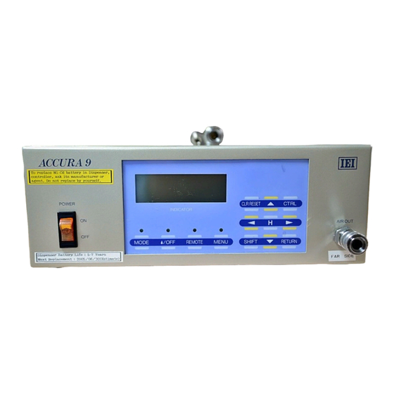
Page 66: Appearance Of The Controller
66 Appearance of the Controller Side view Front view Front view Rear view ACCURA9/9L INSTRUCTION MANUAL...
Need help?
Do you have a question about the ACCURA9 and is the answer not in the manual?
Questions and answers