
Related Manuals for Lotek SRX1200 Series


Summary of Contents for Lotek SRX1200 Series
- Page 1 SRX1200 Receiver U ser Guide For SRX1200 and SRX1200-D Preliminary January 2020, Revision 2...
- Page 2 Contact Lotek for details on updates and upgrades available for the SRX1200 receiver you have selected.
-
Page 3: Table Of Contents
TABLE OF CONTENTS PAGE SECTION I SRX1200 Series TECHNICAL SPECIFICATIONS……………………………......5 RECEIVER CARE, MAINTENANCE AND SERVICE……....... 6 RECEIVER PANEL LAYOUT…………………………......... 7 POWER OPTIONS (Internal & External)…............8 KEYPAD AND DISPLAY…………………………..........9 KEYPAD NAVIGATION (Key Functions) …............10 GAIN AND FREQUENCYADJUSTMENT............12 GPS FIX AQUISITION..................... - Page 4 TABLE OF CONTENTS PAGE CODELOG MODE (continued) FREQUENCY/CHANNEL…………...........24 Frequency Table………………..........25 Adding/Deleting Freq/Channel………........25 Enabling/Disabling Freq/Channel……….......26 Assigning a Transmitter Type…..........26 Master Frequency Table............26 ANTENNA.................... 27 Antenna Groups................ 27 Adding Antennas..............28 Designating a Master Antenna ..........28 Assigning Gain Values............. 29 Scan Priority (Frequency/Antenna/Preview).......
-
Page 5: Srx1200 Series
SECTION I SRX1200 Series... -
Page 6: Technical Specifications
T E C H N I C A L S P E C I F I C A T I O N S Operating Voltage 9 V (+/- 1 V) Range Operating Current 250-450 mA @ 9 V Battery Life Standard: (6 x C cell 1.5 V Alkaline) ~16 hrs. -
Page 7: Receiver Care, Maintenance And Service
• Where applicable, always use the GPS antenna provided by Lotek (3V active antenna) • Always use the AC to DC power adapter provided by Lotek. Avoid using other power supplies, even if they appear to provide the correct 9 V DC voltage. Verify that the overload protection LED on the rear panel green is green. -
Page 8: Power Options (Internal & External)
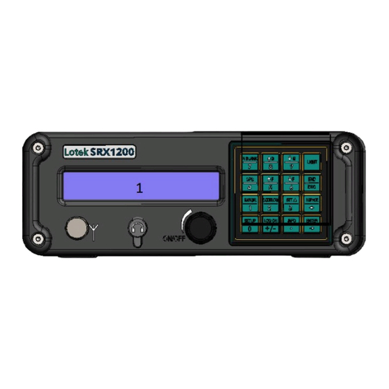
S R X 1 2 0 0 R E C E I V E R L A Y O U T F R O N T P A N E L 1- 2-line 24 Character LCD Display 2 - Topside housing speaker 3 - 16 key membrane keypad 4 - 1/8”... - Page 9 The adapter jack has a circular threaded connector to ensure the power connection to the receiver remains secure. The wall-mount certified (UL, CSA and CE) power supply provided by Lotek accepts 110 V, 60 Hz and 220 V 50...
-
Page 10: Keypad And Display
Hz Adapters must be used to accommodate power requirements specific to each country. Avoid use of generic power adapters. Connecting the external power supply as described disables use of internal battery power. Removing the external power connector re-engages the internal power system to resume the receiver operation if functional batteries are installed. - Page 11 K E Y P A D N A V I G A T I O N FUNCTION ENTER Once a value is entered, pressing the Enter key causes the receiver to accept that entry and save it, provided the receiver is Online. END/ESC The END/ESC key is used for menu navigation, for cancelling incomplete inputs, and for stopping receiver actions in Online mode.
- Page 12 ARROW The Right and Left Arrow keys are used for navigating forwards and KEYS backwards between menu pages. If more than one page is available, a “>” or a “<--” symbol appears in the lower-right corner of the LCD. Multiple pages are used to accommodate the limitations of a two-line display;...
- Page 13 The SRX1200 Gain value range is 0-99 and is applied to increase/decrease receiver sensitivity. Gain value is adjusted/selected using the Up or Down Arrows. The amount of gain increment or decrement can be specified as described on Page 13. The appropriate gain setting depends on prevailing local ambient noise conditions at the intended study set.
- Page 14 GPS DATA ACQUISITION The GPS key enables access to acquire GPS fixes. GPS data can be stored by the receiver either in Monitor mode (manual process) or in Codelog mode (refer to applicable section). GPS fix should be verified before the enabling the GPS feature for a project (refer to Codelog Mode section Enabling/Disabling GPS Positioning), by initiating a scan through Codelog Mode.
-
Page 15: Receiver Operation
R E C E I V E R O P E R A T I O N Upon start-up, the following screen display is typically presented. This screen is displayed when no-one is remotely logged on and the receiver is in its idle (or SETUP) state. - Page 16 Log on to the receiver as follows: Press LOG ON key 1)Log On 2)Log Off Select/press ‘1’ key and ‘Log On’ using default Factory password “123456” Wait a few seconds for changes to be accepted, at which point the receiver will return either to its last active state, e.g.
-
Page 17: Changing/Resetting Password
Offline. This feature is not normally used, except to provide a recovery mechanism if the current password has been lost or forgotten. Should this occur, contact Lotek support staff, provide the receiver serial number and a six-digit number a password will be provided to enable... -
Page 18: Code Set (Selection)
This selection is used if the user intends to track and or log 1) Code Set transmissions from digitally encoded Lotek transmitters. The user selects from a list of code sets that have been installed in the receiver. Three Code Set options are presented. -
Page 19: Codelog & Monitor Mode
window, e.g, 30s, requires that a ‘0’ first be entered. The default value is 30s. CODELOG & MONITOR MODE The key labeled “CODELOG”, or numeric key “2”, accesses the features of the receiver that deal with data collection and the receiver configurations that determine how data is collected OR monitored. - Page 20 CODELOG/MONITOR CONFIGURABLE CHART CONFIGURABLE PARAMETER CHART SRX1200 Model Feature SRX-D1 • • • • Keypad and Display • • • • Mobile tracking • • • Padded Carry Case • • • Pelican Case Housing Bandwidth 12MHz 12MHz 12MHz 26MHz 1MHz 12MHz 26MHz...
-
Page 21: Codelog Configurable Parameters
CODELOG CONFIGURABLE PARAMETERS MONITOR MODE 1)Config (#1) 2)Start 3) Master FTable 1)Config The SRX1200 allows the user to designate up to 8 configurable receiver parameters that determine how the receiver will monitor frequencies of interest and or how data will be collected. Configurations presents a method for creating and storing recurrent project parameters, e.g., frequencies, scan cycle period, antenna scanning, noise blanking, gain, used in a project. -
Page 22: Scan Settings
Enter the number of the desired configuration (between 1 and 8). SCAN SETTINGS Code Set selection Digitally encoded or ‘coded’ Lotek tags transmit four pulses with the individual tag signature defined by the three intervals within the transmission ‘burst’ of these pulses. Every transmitter is assigned a unique code so that it and any sensor data associated with it can be identified by the receiver. -
Page 23: Calculating Total Scan Time
CODELOG MODE CONFIGURABLE PARAMETERS (continued) Calculating Total Scan Time Use the equation below to calculate the Total Scan Time value. ((A x B) x C = Total Scan Time (seconds) where: A = number of radio frequencies B = number of receiver antennas (including the Master) C = scan time (seconds) If a total scan time is not set (left as 00:00), the receiver immediately begins another scan cycle once its scan routine is complete. -
Page 24: Crto
CODELOG MODE CONFIGURABLE PARAMETERS (continued) CRTO CRTO (Continuous Record Time-Out) can be used to conserve memory space. Enabling CRTO allows the receiver to track the number of valid detections for each transmitter ID at a specific frequency and antenna over a fixed time period (CRTO Window). The CRTO Window is defined by the CRTO Timeout as described below. -
Page 25: Gps Clock
CODELOG MODE CONFIGURABLE PARAMETERS (continued) Enable or disable AGC via: CodeLog > 1)Config## > 2)Scan Settings > 3)Options > 3)AGC With AGC enabled, CRTO cannot be used, as gain must be fixed for the duration of a data record window. GPS Clock With the GPS clock the receiver can record and timestamp detection event with a time resolution than when disabled. -
Page 26: Frequency/Channel
CODELOG MODE CONFIGURABLE PARAMETERS (continued) Frequency Table A Configuration Specific Frequency Table is a group of frequencies assigned to a specific configuration. Each of the eight possible ‘Configurations’ (as earlier described) can contain from a single to up to 128 frequencies. From this point forward, the Configuration Specific Frequency Tables are referred to as “frequency tables”. -
Page 27: Assigning A Transmitter Type
CODELOG MODE CONFIGURABLE PARAMETERS (continued) Enabling/Disabling a Frequency/Channel Individual enabled frequencies in a frequency table are available for scanning. Disabled frequencies are not scanned. During a scan, a frequency can be temporarily removed from the scan cycle until needed again. By default, frequencies entered are considered to be enabled. Enable or disable a frequency via: Codelog >... -
Page 28: Antenna
CODELOG MODE CONFIGURABLE PARAMETERS (continued) 3) ANTENNA (ANT) Radio antenna selection can range from simple whip antennas and two- element (H) Yagi antennas common to mobile tracking telemetry applications, to multi- (3-9) element Yagi antennas often selected for use in autonomous datalogging applications. -
Page 29: Adding Antennas
CODELOG MODE CONFIGURABLE PARAMETERS (continued) Adding Antennas Antennas must be added in the order in which they are to be scanned (scan order). For example, the group may be connected to antenna ports 1, 2, 4, and 6, but if they are entered into the receiver in this order: 4, 2, 1, and 6, then that is their scan order. -
Page 30: Assigning Gain Values
CODELOG MODE CONFIGURABLE PARAMETERS (continued) Once a value has been entered, the receiver returns to the menu selection page. Assigning Gain Values The ASP and all antennas must be assigned gain values. A typical starting gain value is 50, but an appropriate value should be set based on local ambient noise conditions and study objectives. - Page 31 CODELOG MODE CONFIGURABLE PARAMETERS (continued) Assign the antenna priority via: Codelog > 1)Config## > 4)Ant > 5)Priority > 1)Freq/Ant Toggling between 1)Freq/Ant applies the corresponding priority to frequency or antenna. Master Antenna Preview feature allows the receiver to conserve power while awaiting a valid detection. Concurrent use of Master Antenna Preview with Total Scan Time affords further power savings (refer to Total Scan Time and TOA section).
-
Page 32: Filters
CODELOG MODE CONFIGURABLE PARAMETERS (continued) 4) FILTERS Received signals can be qualified for storage and display by using a set of filters. This section of the manual describes two filter classes. The first described filter set relates to signals (frequency/channel and transmitter ID) and the second to signal quality (signal strength and pulse timing). - Page 33 CODELOG MODE CONFIGURABLE PARAMETERS (continued) The first entry is shown in the first line of the display. To view the next entry, use the Right Arrow key to advance through the list. An entry in the list can be deleted at any time by pressing the 1 key (1)Del). Accept Channel or ID allows a list of Channel plus tag ID combinations to be created that are to be accepted during scanning operations.
-
Page 34: Echo Filter
CODELOG MODE CONFIGURABLE PARAMETERS (continued) Filters to define pass/fail boundaries based on selected characteristics of pulsed transmissions include: Echo Filter allows a time period entry (in ms) following a valid detection, where any additional pulses within the specified period would be identified as signal echoes and ignored. -
Page 35: Sensors
If there is any question regarding the corresponding values for your tags, please contact Lotek. Sensor Type As coded sensor transmitters can combine up to three sensor types in a single transmitter, the receiver must be able to distinguish among the types. - Page 36 CODELOG MODE CONFIGURABLE PARAMETERS (continued) Entry of Sensor Type values is as described below: Temperature 1. Set minimum temperature via: Codelog > 1)Config > 6)Sensors > 3)Param > 1)C > 1)Min 2. Set maximum temperature via: Codelog > 1)Config > 6)Sensors > 3)Param > 1)C > 2)Max 3.
-
Page 37: Data Download
CODELOG MODE CONFIGURABLE PARAMETERS (continued) Parameter Set the minimum EMG value via: Codelog > 1)Config > 6)Sensors > 3)Param > 4)EMG > 1)Min 2. Set the maximum EMG value via: Codelog > 1)Config > 6)Sensors > 3)Param > 4)EMG > 2)Max 3. - Page 38 Three settings affect the format and size of each data record: • CRTO enabled or disabled • GPS 2D-position feature enabled or disabled • Transmitter Type: ID Only or Sensors While additional fields in a data record are needed to support CRTO, GPS, and Sensor data (or combinations of these), certain data fields are always provided: •...
-
Page 39: Srx1200D Series
SECTION II SRX1200D Receiver Series... -
Page 40: Technical Specifications
T E C H N I C A L S P E C I F I C A T I O N S Operating Voltage Range 9-16VDC (nominal 12V) Operating Current 275 mA @12V Weight ~2.3 kg Size ~27 x 25 x 13 cm Memory 32MB to 128MB Storage Temperature range... -
Page 41: Receiver Care, Maintenance And Service
Store in a cool dry environment. • Always use ear-buds provided by Lotek (stereo plug, 30 Ohm speakers) to obtain audio signal via connection to the ear bud jack on the top panel port. Likewise, use only the GPS antenna (3V active antenna) and connection cables provided by Lotek. - Page 42 S R X 1 2 0 0 D - S e r i e s R e c e i v e r L a y o u t T O P P A N E L 1 (Under lid) 1 - Magnetic Actuator to auto-disable LEDs 2 - Instructions for Operation Label 3 - LED Indicators...
- Page 43 SRX1200-D Model Description The SRX1200-D is designed to be externally powered from a 9-16VDC supply source for autonomous data collection of either VHF beeper or Lotek coded transmitters. Three receiver models are available with distinguishing features as shown below. All SRX1200D models support GPS clock synchronization and scanning at up to four antennas.
- Page 44 VHF Antenna Connectors The SRX1200D supports antenna switching using up to four individual BNC VHF antenna ports labeled A1, A2, A3, and A4. Antennas may be designated as Masters and may be monitored either sequentially or simultaneously , depending on application requirements.
-
Page 45: Wake Up Sleep Utility
Wake Up Sleep Utility The Wake Up Sleep feature is a scheduling utility that allows the user to define start and stop (on/off) periods of operation for the receiver over a 24 hour cycle period with one hour interval resolution (as shown). In its stop or off state, no monitoring or data logging activity occurs. - Page 46 A : A P P E N D I X D D I T I O N A L N F O R M A T I O N A n n e x e A : I n f o r m a t i o n C o m p l i m e n t a i r e s A.
- Page 47 20 cm de toutes les personnes. A R N I N G S Changes or modifications not expressly approved by Lotek Wireless Inc. could void the user's authority to operate the equipment. M I S E S E N G A R D E Les changements ou modifications non expressément approuvés par Lotek Wireless Inc.
Need help?
Do you have a question about the SRX1200 Series and is the answer not in the manual?
Questions and answers
Tag id says 999 what am I doing wrong
A tag ID of 999 indicates interference or anomalies in the data and is considered an unknown or unintelligible ID.
This answer is automatically generated