Advertisement
Quick Links
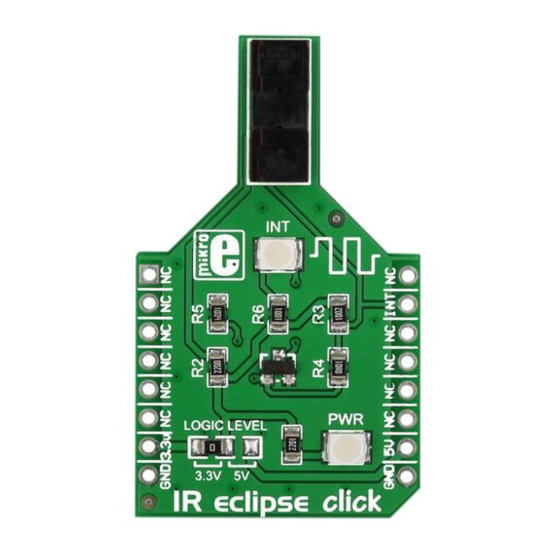
IR eclipse
click
™
1. Introduction
IR eclipse click
carries an EE-SX198 photo
™
interrupter sensor. This sensor consists of
an infrared transmitter and receiver facing
each other and spaced apart by a 3mm
slit. When the beam from the transmitter
is eclipsed with by placing an object in the
gap (like a piece of paper), the sensor is
activated (indicated by the onboard INT
LED). IR eclipse click
communicates with
™
the target board through the mikroBUS
INT line. It's designed to work with either
a 3.3V or 5V power supply.
2. Soldering the headers
Before using your click
board, make sure
™
to solder 1x8 male headers to both left
and right side of the board. Two 1x8 male
headers are included with the board in
the package.
2
Turn the board upside down so that
the bottom side is facing you upwards.
Place shorter pins of the header into the
appropriate soldering pads.
™
1
3
Turn the board upward again. Make sure
to align the headers so that they are
perpendicular to the board, then solder
the pins carefully.
3. Plugging the board in
Once you have soldered the headers your
board is ready to be placed into the desired
mikroBUS
™
socket. Make sure to align the
cut in the lower-right part of the board with
the markings on the silkscreen at the
mikroBUS
socket. If all the pins
™
are aligned correctly, push the
board all the way into the socket.
4. Essential features
Photo interrupter sensors are typically
used in printers, copiers, vending machines,
for optical limit switches and so on. You
can implement IR eclipse in your design
wherever there's a need to detect the
position of a moving part, whether you need
to detect if said part is in correct place, or to
infer speed of rotation — as long as its thin
enough to fit in the 3mm-wide slit where
the infrared beam passes through.
click
™
BOARD
www.mikroe.com
IR eclipse click
™
manual
ver. 1.00
0 100000 027301
Advertisement

Related Manuals for mikroElektronika IR eclipse click MIKROE-1711


Summary of Contents for mikroElektronika IR eclipse click MIKROE-1711
- Page 1 2. Soldering the headers Before using your click board, make sure ™ to solder 1x8 male headers to both left and right side of the board. Two 1x8 male headers are included with the board in the package. IR eclipse click ™...
- Page 2 MikroElektronika assumes no responsibility or liability for any errors or inaccuracies that may appear in the present document. Specification and information contained in the present schematic are subject to change at any time without notice. Copyright © 2014 MikroElektronika. All rights reserved.
Need help?
Do you have a question about the IR eclipse click MIKROE-1711 and is the answer not in the manual?
Questions and answers