
Related Manuals for Aspar 8AI

Summary of Contents for Aspar 8AI
- Page 1 RS485 MODBUS Module 8AI Expansion Module – 8 analog inputs Version 1.5 User Manual Manufactured for...
- Page 2 RS485 MODBUS Module 8AI User Manual Thank you for choosing our product. This manual will help you with proper support and proper operation of the device. The information contained in this manual have been prepared with utmost care by our professionals and serve as a description of the product without incurring any liability for the purposes of commercial law.
-
Page 3: Safety Rules
2. Module Features 2.1. Purpose and description of the module 8AI module allows measurement of voltages and currents. Values are read via RS485 (Modbus), so we can easily integrate the module with popular PLCs, HMI or PC equipped with the appropriate adapter. -
Page 4: Technical Specifications
RS485 MODBUS Module 8AI User Manual 2.2. Technical Specifications Voltage 10-38VDC; 10-28VAC Power Supply Maximum Current 120 mA @ 12V / 100 mA @ 24V No of inputs Voltage input 0V to 10V (resolution 1.5mV) Voltage input -10V to 10V (resolution 1.5mV) Voltage input 0V to 1V(resolution 0.1875mV) -
Page 5: Dimensions Of The Product
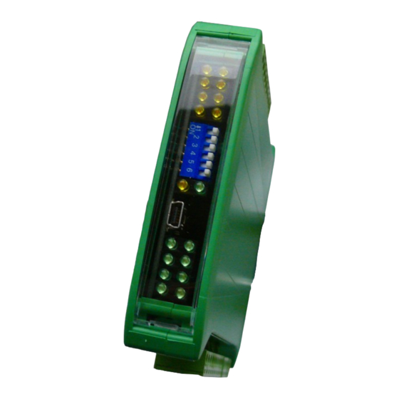
RS485 MODBUS Module 8AI User Manual 2.3. Dimensions of the product Look and dimensions of the module are shown below. The module is mounted directly to the rail in the DIN industry standard. Power connectors, communication and IOs are at the bottom and top of the module. USB connector configuration and indicators located on the front of the module. -
Page 6: Communication Configuration
RS485 MODBUS Module 8AI User Manual 3. Communication configuration 3.1. Grounding and shielding In most cases, IO modules will be installed in an enclosure along with other devices which generate electromagnetic radiation. Examples of these devices are relays and contactors, transformers, motor controllers etc. This electromagnetic radiation can induce electrical noise into both power and signal lines, as well as direct radiation into the module causing negative effects on the system. -
Page 7: Types Of Modbus Registers
RS485 MODBUS Module 8AI User Manual 3.4. Types of Modbus Registers There are 4 types of variables available in the module Beginning Modbus Type Variable Access address Command 00001 Digital Outputs 1, 5, 15 Read & Write 10001 Digital Inputs... -
Page 8: Configuration Registers
RS485 MODBUS Module 8AI User Manual 3.5.3. Configuration registers Modbus Name Values Address 0 – 2400 1 – 4800 2 – 9600 3 – 19200 40003 0x02 Baud rate 4 – 38400 5 – 57600 6 – 115200 other – value * 10 0 –... -
Page 9: Module Connection
RS485 MODBUS Module 8AI User Manual 5. Module Connection Expansion Module – 8 analog inputs User Manual Version 1.5 9 / 15... -
Page 10: Switches
RS485 MODBUS Module 8AI User Manual 6. Selecting the input mode Each input can be used to measure the voltage (the default) or current. To change the operating mode in addition to configuration changes by using the program, also set the... -
Page 11: Modules Registers
RS485 MODBUS Module 8AI User Manual 8. Modules Registers 8.1. Registered access Modbus Register Name Access Description 30001 0x00 Version/Type Read Version and Type of the device 30002 0x01 Switches Read Switches state 40003 0x02 Baud rate Read & Write... - Page 12 RS485 MODBUS Module 8AI User Manual Modbus Register Name Access Description 40074 0x49 MIN alarm level 4 Read & Write 40075 0x4A MIN alarm level 5 Read & Write 40076 0x4B MIN alarm level 6 Read & Write 40077 0x4C MIN alarm level 7 Read &...
-
Page 13: Bit Access
RS485 MODBUS Module 8AI User Manual 8.2. Bit access Modbus Register name Access Description Address Address Address 0x320 Input 1 Read Set when the input is connected 0x321 Input 2 Read Set when the input is connected 0x322 Input 3... -
Page 14: Configuration Software
RS485 MODBUS Module 8AI User Manual 9. Configuration software Modbus Configurator is software that is designed to set the module registers responsible for communication over Modbus network as well as to read and write the current value of other registers of the module. This program can be a convenient way to test the system as well as to observe real-time changes in the registers. -
Page 15: Table Of Contents
RS485 MODBUS Module 8AI User Manual Table of Content 1. Safety rules............................3 2. Module Features..........................3 2.1. Purpose and description of the module..................3 2.2. Technical Specifications......................4 2.3. Dimensions of the product......................5 3. Communication configuration......................6 3.1. Grounding and shielding......................6 3.2. Network Termination........................6 3.3. - Page 16 Voltage Current Input No input input (default)
Need help?
Do you have a question about the 8AI and is the answer not in the manual?
Questions and answers