Advertisement
Table of Contents
Advertisement
Table of Contents

Subscribe to Our Youtube Channel
Related Manuals for WaterFurnace GeoLink FC1-GL

Summary of Contents for WaterFurnace GeoLink FC1-GL
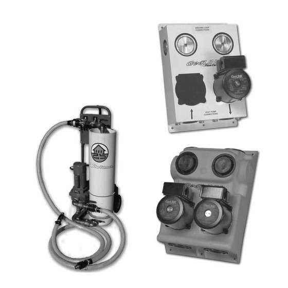
- Page 1 Flow Center Installation and Loop Flushing Flow Centers (FC1-GL, FC2-GL, FC1-FPT, FC2-FPT, FC1-FPTB & FC2-FPTB) Flush Cart (LFC-F) Flow Center Installation Electrical Flushing and Charging Procedures Unit Pressure Drop Tables Antifreeze Use Troubleshooting IM1961 06/08...
-
Page 2: Nomenclature
FLOW CENTER INSTALLATION AND LOOP FLUSHING MANUAL Flow Center Model Nomenclature 1 - GL Flow Center Type GL = 1˝ GeoLink Connections Number of Pumps w/high impact polystyrene cabinet FPT =1˝ Female Pipe Thread Connection w/metal cabinet FPTB = 1˝ Female Pipe Thread Connections w/bronze volute &... -
Page 3: Table Of Contents
FLOW CENTER INSTALLATION AND LOOP FLUSHING MANUAL Table of Contents Nomenclature General Installation Information Electrical Flush Cart Information Flushing and Charging 11-14 Initial Start-up 15-16 Unit Pressure Drop Tables 17-18 Troubleshooting Antifreeze Selection and Use 20-21 Pipe Pressure Drop 22-23 Loop Pressurizer... -
Page 4: General Installation Information
FLOW CENTER INSTALLATION AND LOOP FLUSHING MANUAL General Installation Information Safety Considerations WARNING: Before performing service or maintenance operations on the system, disconnect all power sources. Electrical shock could cause personal injury. Before applying power, make sure that all covers and screws are in place. - Page 5 FLOW CENTER INSTALLATION AND LOOP FLUSHING MANUAL General Installation Information (cont.) Connection Options Fitting(s) Rubber Hose Kit " MPT to 1" barbed (PVC or brass) " MPT to 1" glue socket or 1" MPT nipple Use brass barbs and double clamp or PE to brass adapter Copper 1"...
- Page 6 FLOW CENTER INSTALLATION AND LOOP FLUSHING MANUAL General Installation Information (cont.) Figure 2a: FPT Style Flow Center 12.38” 1” FPT Fittings 4.25” (4 Typical) 1" FPT Access GROUND LOOP Ports for CONNECTIONS Flushing Three Way Valve Position Indicator 13.58” HEAT PUMP CONNECTIONS 3.25”...
- Page 7 FLOW CENTER INSTALLATION AND LOOP FLUSHING MANUAL General Installation Information (cont.) Figure 2b: GL Style Flow Center TYPE SHIPPING WEIGHT INCHES 15.0 10.3 14.0 FC1-GL 26 LBS [CM] [38.1] [26.0] [17.8] [35.6] [5.1] [6.7] [12.7] [11.4] FC2-GL 31 LBS...
- Page 8 FLOW CENTER INSTALLATION AND LOOP FLUSHING MANUAL Electrical Information Single-Speed Units Figure 3: Single Speed Field Unit Wiring for Loop If a single-speed unit is to be used, the pump(s) will be con- Pumps nected to the terminals on PB1 in the unit electrical box as shown in Figure 3.
-
Page 9: Electrical
FLOW CENTER INSTALLATION AND LOOP FLUSHING MANUAL Electrical Information (cont.) Multiple Units On One Flow Center When two units are connected to one loop pumping system, pump control is automatically achieved by connecting the SL terminals in both units with 18-gauge 2-wire thermostat wire. These terminals are polarity conscious (see Figures 5 and 6 for proper loop pump SL wiring). -
Page 10: Flush Cart Information
FLOW CENTER INSTALLATION AND LOOP FLUSHING MANUAL Flush Cart Information The WFI Flush Cart has been designed to effectively and effi ciently fl ush geothermal earth loops and to facilitate mixing and injection of antifreeze. The single most important element in fl ow center pump reliability is the ability to remove all the air from the earth loop and provide the proper working pressure. -
Page 11: Flushing And Charging
FLOW CENTER INSTALLATION AND LOOP FLUSHING MANUAL Flushing & Charging All fl ushing of earth loops should be performed using Figure 8: Loop and Unit Flushing a 1.5 hp (1.1 kW) or larger pump. The manufacturer markets a fl ush cart designed specifi cally for earth loops. Flushing can be accomplished using three different methods. - Page 12 FLOW CENTER INSTALLATION AND LOOP FLUSHING MANUAL Flushing & Charging (cont.) Flushing and Filling Earth Loop and Unit(s) Together All air and debris must be removed from the earth loop piping system before operation. Flush the loop with a high vol- ume of water at a high velocity (.6 m/s) (2 fps in all piping).
- Page 13 FLOW CENTER INSTALLATION AND LOOP FLUSHING MANUAL Flushing & Charging (cont.) To Flush Loop Only Connect loop to fl ow center. Connect the unit side connections of the fl ow center together with a jumper. Remove caps from fl ow center access ports. Connect fl...
- Page 14 FLOW CENTER INSTALLATION AND LOOP FLUSHING MANUAL Flushing & Charging (cont.) To Flush Unit Only: (Used When Replacing Unit, Coax, Hose Kit or Pump) Connect unit to fl ow center. Rotate 3-way valves to isolate ground loop and gain access to unit side only as shown in Figures 11a and 11b. Remove access port caps/plugs and install boiler drain adapters for garden hose connection to the fl...
-
Page 15: Initial Start-Up
FLOW CENTER INSTALLATION AND LOOP FLUSHING MANUAL Flow Center Initial Startup Startup of Flow Center Check to make sure that the loop and unit isolation valves are completely open and the fl ush ports are closed and sealed. Check and record the earth loop pressure: Loop Pressure = In _____ Out _____ Check and record the fl... - Page 16 FLOW CENTER INSTALLATION AND LOOP FLUSHING MANUAL Flow Center Initial Startup (cont.) Pressure/Temperature Plugs The pressure/temperature plugs (P/T plugs) supplied with the earth loop connector kit are provided as a means of mea- suring fl ow and temperature. The water fl ow (GPM or L/S) through the unit can be checked by measuring the incoming wa- ter pressure at the supply water P/T plug and subtracting the leaving water pressure at the return water P/T plug.
-
Page 17: Unit Pressure Drop Tables
FLOW CENTER INSTALLATION AND LOOP FLUSHING MANUAL Unit Pressure Drop Tables Residential Unit Pressure Drop Closed Loop (minimum) Closed Loop (optimum) Series Model & Size Flow Rate Pressure Drop* Flow Rate Pressure Drop* Ft. Head Ft. Head * Pressure Drops shown at NS022 50º... - Page 18 FLOW CENTER INSTALLATION AND LOOP FLUSHING MANUAL Unit Pressure Drop Tables (cont.) Residential Unit Pressure Drop (cont.) Closed Loop (minimum) Closed Loop (optimum) Series Model & Size Flow Rate Pressure Drop* Flow Rate Pressure Drop* Ft. Head Ft. Head V(L/X)009 V(L/X)012 14.1 V(L/X)015...
-
Page 19: Troubleshooting
FLOW CENTER INSTALLATION AND LOOP FLUSHING MANUAL Troubleshooting PROBLEM POSSIBLE CAUSE CHECKS AND CORRECTIONS Water drips out Condensation Insulate piping. Water leak Tighten connections. Low fl ow / No fl ow No power Check power supply from the unit. Blow fuse Replace fuse - check for cause. -
Page 20: Antifreeze Selection And Use
FLOW CENTER INSTALLATION AND LOOP FLUSHING MANUAL Antifreeze Selection And Use “P” Series/ “E” Series equipment includes freeze protection thermistors to protect the water-to-refrigerant heat exchang- er (coax) from damage caused by freezing liquid. Be sure the “Loop/Well” DIP switch is in the “Loop” position if antifreeze is used and in the “Well”... - Page 21 FLOW CENTER INSTALLATION AND LOOP FLUSHING MANUAL Antifreeze Selection and Use (cont.) Figure 14: Freeze Protection Curves P/N: CAMT Methanol Hydrometer Methanol Mixture 0.900 Environol™ Mixture 1.00 Freeze Protection Temperature ( ˚F) * With reference to 60°F water courtesy of Carbide and Carbon Chemicals Corporation 1.000 Figure 15: Environol™...
-
Page 22: Pipe Pressure Drop
FLOW CENTER INSTALLATION AND LOOP FLUSHING MANUAL Pipe Pressure Drop WATERFURNACE POLYETHYLENE PRESSURE DROP PER 100 FT OF PIPE IN FEET OF HEAD ALL SIZES SDR 11 BRINE 25% ETHANOL @ 30°F Viscosity 0.004 lbm/ft sec Darcy-Weisbach Method Density 61.30 lb/ft3 3/4”... -
Page 23: Loop Pressurizer
FLOW CENTER INSTALLATION AND LOOP FLUSHING MANUAL Pipe Pressure Drop (cont.) WATERFURNACE PRESSURE DROP PRESSURE DROP PER 100 FT. OF PIPE IN FEET OF HEAD PER 100 FT OF HOSE IN FEET OF HEAD CSA 100 and 160 SERIES PE PIPE... - Page 24 Fort Wayne, IN 46809 Product: Flow Center Installation and Loop Flushing Type: FC1-GL, FC2-GL, FC1-FPT, FC2-FPT, FC1-FPTB and FC2-FPTB. LFC-1 WaterFurnace Renewable Energy has a policy of Document Type: Installation Manual continuous product research and development and Part Number: IM1961...
Need help?
Do you have a question about the GeoLink FC1-GL and is the answer not in the manual?
Questions and answers