
Subscribe to Our Youtube Channel
Related Manuals for Elektro-Automatik EL 3000A Series

Summary of Contents for Elektro-Automatik EL 3000A Series
- Page 1 操作说明书 Instruction Manual EL 3000A Electronic DC Load 直流电子负载 400W Doc ID: EL3CN EL 3160-60A: 35 320 200 Revision: 14 EL 3400-25A: 35 320 201 Date: 05/2017...
- Page 3 概述 关于 安全须知 Elektro-Automatik GmbH & Co. KG Helmholtzstrasse 31-33 41747 Viersen 请仅在铭板标示电压下操作本仪器。 • Germany 请勿将任何机械零件,特别是金属件,插入仪器内,否 • 则将有触电危险或损坏仪器。 +49 2162 / 37850 电话: 请避免在仪器周围使用任何液体物质,因有可能进入仪 • +49 2162 / 16230 传真: 器内部并损坏它。 www.elektroautomatik.cn 网址: 请勿将高于负载额定电压的电压源连接到负载上。比如 • ea1974@elektroautomatik.cn 邮箱: 80V型号的负载,不能连接高于100V的电压源,160V 型号不能连接高于180V的电压源,400V的产品不能连 © Elektro-Automatik 接460V电压源。...
-
Page 4: Table Of Contents
目录 页面 1. 介绍 ....................5 2. 技术规格 ..................5 2.1 控制面板 ..................5 2.2 各产品型号详细规格 ................6 3. 外观 ....................7 3.1 前视图 ..................7 3.2 后视图 ..................7 3.3 供应清单 ..................8 4. 基本信息 ..................8 4.1 序言/警告 ..................8 4.2 与主电源的连接/接地 ................8 4.3 制冷 ..................8 4.4 拆卸 ..................8 4.5 温控关断/通风... -
Page 5: 技术规格
关于产品 1. 介绍 2. 技术规格 实验室用EL3000A系列电子负载为极其高效之产品,在一 控制面板 小巧外壳内给用户提供多种有趣的特性。除电子负载的一 般功能外,本产品可以在脉动模式下测试电池、加载电压 或电流源,其脉冲宽度和幅度皆可调。您也可通过接口卡 型号 遥控本产品,通过电脑几乎能控制和监控其所有功能。 80个字符,两行显示的LCD 显示器: 通过一接口卡,能轻易将电子负载合并到现有远程控制 系统,并且非常直观地完成产品的配置。也可经产品后 2个旋钮,2 个旋转开关, 运行元素: 面的模拟接口插座,或通过带模拟接口的任何其它设备 1个按钮 来控制和监控。 显示格式 利用某一款接口卡即可简便地将本产品整合到现有系统 标称值决定可调范围。 内,配置非常直观,在产品上可全部完成。故本系列电 子负载可结合PS9000/PSI9000系列电源一起操作,或者 只要当前运行操作模式允许,可一次性显示实际值和设定 利用电子负载后板安装的额外接口,用带模拟接口的其它 值。 产品来控制和监控。 本产品由微处理器控制,得以使产品能准确、快速地测量 电压值显示 和显示出各实际值,并具备一般标准模拟技术不能实现的 3或4位数 分辨率: 多项新扩展可操作性功能。 0.0V…999.0V 格式: 现代化的设计赋予产品最高性能的同时,也实现了在节 省的空间内进行复杂和有效应用的理念,比如:为符合... -
Page 6: 各产品型号详细规格
关于产品 各产品型号详细规格 EL3160-60A EL 3400-25A 主电源输入 115V/230V ±10%, 可转换 115V/230V ±10%, 可转换 输入电压 输入频率 50/60Hz 50/60Hz 输入保险 M0.63A M0.63A 直流输出 输入电压 U 160V 400V 输入功率 P 400W 400W 输入电流 I 过压保护极限 1.1 * U 1.1 * U 允许最大输入电压 180V 450V 电压控制... -
Page 7: 前视图
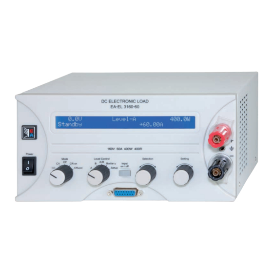
关于产品 3. 外观 前视图 图 1 后视图 图 2 AUX端子的引脚分布说明: +S = 正感测输入端 (+) -S = 负感测输入端 (-) Gnd = 触发输出接地端 Tr = 触发输出端* * 由Level A/B操作模式下的设定形成的方波从该引脚输出,代表决定内 部触发信号的脉宽。 EL 3000 A 系列 日期:05-30-2017 产品说明书... -
Page 8: 供应清单
关于产品 供应清单 动态特性和稳定准则 1 x 电子负载 本电子负载特征在于由内部调整线路高带宽形成的短暂 电流升降时间。 1 x 印刷版使用说明书 如果负载连上带有自身调整线路的测试源,如电源,可 1 x 电源线 能出现调整不稳定现象。这个不稳定性是整个系统(馈源 和电子负载)在特定频率下的相数和增益余量太少而形成 的。180°相位位移在>0dB的放大条件下,会导致振荡或 4. 基本信息 不稳定。如果连接线是高导电性的或电感-电容性的, 无调整线路的使用源(如:电池)也可能出现相同情况。 序言/警告 此不稳定性不是负载的误操作造成,而是整个系统的动 本操作说明书和产品专给对本电子负载有基本了解的人士 作。改善后的相和增益余量可解决此问题。特别是在负载 使用。本产品不应给无基本电器知识的人士操作,因本说 直流输入端直接装个电容的方法,建议用1µF,比较低的 明书未作此方面解释。操作不当和未遵守安全说明的操作 系统可用100µF电容。 可能会损坏产品或丧失产品保修权利! 调整线路不可将内阻调至,这也可防止在很低输入电压时 输出最大输入电流。请见下列图解。第一个图描述了至少 与主电源的连接/接地 需要的输入电压,才能获得最大电流。 本产品通过电源线接地,因此只可与带接地片的电源插座 使用。 千万不可用无接地的延长线打断线路! 阻值调整(U 比例) Widerstandsregelung (Verhältnis Ue/Ie) Widerstandsreg 60A负载... -
Page 9: 与市电的连接
关于产品 5. 安装 目检 收到本产品后,请检查是否有外观受损痕迹。如有,请不 要操作本产品,应立即联系您的供应商。 与市电的连接 使用随附于产品的电源线与市电相连。 电源插座为IEC320型10A插座,电源线长1.5m,导体直 径为 3 x 0.75mm²。 本产品装有5x20mm的保险丝(M0.63A),从后面板可拆 装更换。 直流输入端 负载器的输入端位于产品后面。在此处用Bueschel插头 或螺丝与夹子固定与任何馈源的连接。请随时注意设备 的正确极性!仅允许连接直流电压! 产品的输入端并无容丝装置。为避免馈源损坏负载器, 应随时注意电子负载器的标称值。如有必要,特别是在 给电池放电时,可在负载器和馈源之间加装一额外的保险 丝。 负载线的直径随输入电流而定。我们建议这样使用: 2 x 1mm² 或至少 1 x 4mm² 针对25A以下产品: 2 x 6mm² 或至少 1 x 16mm² 针对60A以下产品: 针对每根线(弹性线)。... - Page 10 关于产品 6. 操作 也可参考第章节3.1所有操作元素综述。 显示 下面为两行显示屏的总图和布局。左图通常显示负载输 入启动后的实际值: 图 3 报警管理器 调整模式指示符号(三角形)出现于实际值旁边,它与负载 器当前运行的调整模式相关。如果某标称值超标,根据选 Overvoltage,Overtemperature或Power fail信号指示 定的不同调整模式而不同。限流或限功率要优先于限电压 出有错误出现。 或限阻值。这表示,只要标称电流被超过,负载即转至恒 如果市电输入电压太低,会出现power fail(断电)报 流限制,三角形符号将会出现而指示出来。 警。如果直流输入过压极限被超越(见„2.2 各产品型 在待机(负载输入关闭)情况下,显示Standby状态,并 号详细规格“),会出现overvoltage(过压)报警。 只显示实际电压值: 这两种错误都会关闭负载输入,直到错误排除后方可重 新启动。overtemperature报警表示产品内部过热,会 暂时关闭直流输入,知道功率模块再次冷却后方打开。 报警指示一直显示于屏幕上,直至被确认方消失。此目的 图 4 在于告知用户报警仍然存在或已消失。举例: 显示屏右半边的这部分内容指示不同的操作模式和错误 种类: 图 7 被激活的报警信息总是优先于消失的报警信息。如果两 图 5 个报警都出现,那么过压要优先于断电而出现在显示屏 当负载器通过可选接口卡设置在远程控制模式下(Remote mode)时出现这部分内容。在模式则可能为Level A, B 上。...
-
Page 11: 操作元件
操作产品 Battery 操作元件 关闭负载,激活电池测试模式。 Setup 关闭负载,激活设置菜单。在此处设置产品 和接口卡(如果装有的话)。 更多关于操作模式的内容请参考章节„6.7 Level A和 主电源开关Power (1) Level B的使用“。 用于打开或关闭负载器。 Input on/off (4)按钮 用于激活或停用负载操作(即:开/关输入) 。输入关闭通过Standby指示于显示屏上。输 选择器Mode (2) 入的打开可能会因某些原因被阻止。比如:错 用于预选产品即将将运行的调整模 误出现,或通过模拟接口的REM-SB引脚阻止 式。不同的调整模式会相互影响。 了输入的传输。 一旦实际值达到设定值,调整模式 在电池测试模式下按下本按钮,计时终止或继续,从而 就会改变。这会导致,即使之前已 打开或关闭输入。 设置恒流控制(CC)为运行模式, 用它还能确认显示屏上的报警信息。按下本按钮,显示 而恒功率控制(CP)模式却能占主 的错误信息被清除(只要不再有激活的报警),于是可照 导地位。当前运行的调整模式显示在显示屏上。更多关 常使用其它功能。 于各调整模式的内容请见章节„6.6 预选调整模式“。 在远程操作下,即数字接口卡控制模式下,按住按钮 有下列可选模式:... -
Page 12: 打开Input On/Off开关
关于产品 如果Keep set values参数被设为no,手动转换至CC调 打开input on/off开关 整模式可将功率设定值恢复至其标称值,电流设定值为 按下Input on/off (4)按钮,直流输入打开,产品开始以 0。如果是yes,保留调整最小的设定值。详情见„7.1 设 负载器工作。 置菜单“。 再次按下按钮,输入关闭。 是指恒压。此时可调节电压、电流和功率设定值。 如果负载之前已被启动,通过模拟接口(pin = low)叫 „REM-SB“的引脚可关闭输入。如果负载之前已被关 在此模式下,接载太多馈源会引起输出电压爆跌,输入 电压会被调整并限定为调节值,如果馈源能输出大于负 闭,则不可再打开输入。 载能吸收的电流,则不能达到电压极限。 负载工作时,电流、电压、功率和阻抗所有这4个实际 如果Keep set values参数被设为no,转到CV模式后, 值都显示在屏幕左半边。 可将电压、电流和功率设定值重设为标称值。如果是 负载输入关闭时,只显示实际电压值,因为此时无其它 yes,保留调整最小的设定值。详情见„7.1 设置菜单 合理的实际值。在电池测试模式按下本按钮,计时器停 “。 止。 注意:CV调整不能与电池测试模式一起使用。如果选了 负载操作的激活可因某些原因而被阻止。比如:出现过 电池测试,显示屏会出现错误信息。 压或其它错误,或负载由模拟或数字接口远程控制(接口 注意:给CV调整模式配置的设定电压,在其它任何模式 卡)。... -
Page 13: Level A和Level B的使用
关于产品 Level A和Level B的使用 6.7.3 Level A/B (脉动操作) 这个模式将A和B的两组设定值组合在一起,而且A和B各 介绍 自的可调脉宽都不同。电子负载通过这些数值自动生成A Level A和Level B代表两组不同的可以转换的设定值,以 和B间的设定值阶跃,且其上升/下降时间可调。脉动操 便产生一设定值台阶。可通过Level Control (3)选择器手 作只适合应用属于被选模式的设定值。意思是,在CV模 动转换,或者通过带触发输入的模拟接口从外部转换,或 式下,只有电压会受影响,而其它设定值保持不变。详 者自动转换(A/B模式)。 情请参考图11和12。 A和B都有对应4个调整模式的5组设定值。意思是电流设 A的脉宽对应A的设定值。脉宽总和形成一个时间段t,它 定值对应恒流模式。例如:在CP模式下,您可以调节功 代表一定的频率f=1/t。脉宽在50µs...100s间可调,从而形 率的两组设定值,在他们之间进行切换,产生功率台阶。 成100µs...200s的时间段,对应10kHz...0.005Hz频率段。 使用A/B模式时(见6.7.3),连同A和B的可调脉宽(即: 注意:像OVP或PF(缺电)(见章节6.1的“报警管理器”) 脉冲时间)进行自动转换。这时产生方波设定值,其高级 一样可关闭输出的报警也终止脉动操作。而且只要报警 别以A值来表示,低级别以B值表示,时间段(或频率)以 被确认并清除方可恢复。 A和B的可变脉宽总和表示。这些也决定所谓的占空比。 举例:A = 10ms,B = 90ms,得出100ms(= 10Hz)时间 External trigger 段的10%占空比。见图11. -
Page 14: 升/降时间
关于产品 注意:Level A/B操作模式下适应下列:Level A的设定值 电池测试模式 必须始终大于或等于Level B的。因此可将A向下调至B,将 介绍 B向上调至A。如果发现Level A好像不能调了,可能已经 „Battery“模式指对电池进行测试,将电池连到负载上, 达到Level B的相同值。 对电池定义性地放电。测量平均电流,计算累计时间, 然后将消耗容量以AH显示出来。电压监控和可调欠压一 起关闭Ulow极限,防止电池过放。这个极限需调整至少 一次。如果测试过程中超过极限,负载输入自动关闭, 计时器终止。电池不再输出电流。如果极限大于电池电 压,测试则不能开始。 选择调整模式 可在任何时候更改调整模式,即使正在运行测试也可以。 该操作可重设整个测试,包括计时器和Ah值。 使用 测试之前和测试过程中都可进行调整模式设定值的调节, 欠压会关闭Ulow极限。用Selection(5)选定设定值。用 Setting(6)调节。显示器以小时:分:秒(HH:MM:SS)的 格式显示累计时间,以Ah为单位显示消耗容量。 图 12 计算Ah值 图图12显示了设定值((U, I, P或 R) ,可调脉宽和可变振 安培小时值(吸取的电荷)是最后两次测得的输入电流的平 幅的变化图。升/降时间也可调,但A和B值相等。 均值乘以所用时间而计算出来的。 如果升/降时间设至最小,脉动操作的信号接近理想方波 开始/暂停/停止测试 形状。图12只是一个阐述图。举一个实际变化的例子:... -
Page 15: 报警管理器
关于产品 终端控制区域和优先顺序 控制区域是指产品被控制的区域。这有可能在产品本身( 手工控制),可能通过模拟接口(外部控制)或通过接口卡 (遥控)。为防止用户一次性从两个区域访问负载器而设 置了优先顺序。适用如下: 模拟接口具有最高优先权,数字接口第二,手动控制最 低。意思是如果产品被设为遥控,则不可用开关和旋钮 设置模式和设定值。如果在遥控运行同时转换到外控,遥 控状态将被重设,负载只能通过模拟输入控制。为了将此 报告给电脑上运行的软件,尝试访问和控制负载器,控制 区域内部设为“local”。在“local”状态下负载器能通过 电脑读取(即:监控)。 6.10 串联和并联连接 多台负载可以并联,但也不是完全支持。意思是,并联时 电流不会自动分配。故用户需注意正确控制产品。 并联操作时,通过控制板或接口卡(数字或模拟)对并 联中所有产品的U,I,P和R调节成相同数值,从而达到平 均分配的效果。 注意!本系列产品不可串联!否则产品会受损。 EL 3000 A 系列 日期:05-30-2017 产品说明书... -
Page 16: 产品配置
操作设置 基本ID(如下)开始,在整个ID范围(11位元, 0...2047) 7. 产品配置 内可调节四个阶段。另外一个ID作为广播ID,它区别于其 设置菜单 它三个基本ID。 除非处于遥控模式,仅能用Level(3)选择器打开设置菜 normal Vector 提示:根据 或 设定,后面的参数也会变换。 单。当负载处于设置菜单时,不可进行正常的负载操作。 CAN Relocatable ID 显示屏根据安装的接口卡型号显示一系列参数。这些参 可能性设置:0...31 数可由Selection(5)选定并由Setting(6)改变。显示屏右 边的两个小三角形指示还有更多参数。显示屏第一行进 默认设置:0 一步显示安装卡的型号,如:IF-U1 属于:CAN接口卡IF-C1 解释:本设置决定产品CAN ID所处的(可再定位)地址 段。要了解更多信息请参考基本的CAN技术规格。举例: 电子负载由于某些原因指定为地址5,这可能与另一有相 图 14 同地址的总线相抵触,您可以将这个地址通过定义RID( 接着第二行显示由Selection(5)选定的所有参数。这些参 可再定位ID的缩写)移到另一地址段,这样就不会有抵触 了。因此使用CAN时,理论上有32 x 30个可能的产品节 数根据是否配有接口卡而会不同。 点(每个为两各ID)。 有下列设置: Trigger mode CAN Base ID (自5.01固件版本才有) -
Page 17: 模拟接口
远程控制 VREF输出端用于生成VSEL,CSEL,PSEL和RSEL设定 8. 模拟接口 • 值。举例:如果只需要CC调整模式,VSEL设定输入 介绍 必须固定为0V,通过0-10V外部源或可调电位器(GND 模拟接口为一个位于产品后面板的带15个引脚的Sub-D 和VREF,滑动开关至CSEL)给PSEL,VREF和CSEL 插座,专用于通过外部硬件 (如:开关电源,开关,继 供电。见下表。 电器)遥控电子负载的最重要功能。 Level A/B模式下可调升/降时间和脉宽此时失效。如 • 负载必须转至外部控制以便使用模拟接口。需要连一跳 果期望得到某种形式的振幅-时间-进度,通过一外部 线(或开关)在第7引脚(远程)和第6引脚(接地)之间。于 函数发生器产生和输入。 是显示屏显示状态如下: mode)下触发输入无 在模拟接口控制模式(External • 功能。即只能由输入设定值输入端的信号产生设定值 跃变。 配置举例 图 15 下表列举了多个单一或组合调整模式的设置。如果不使 优先顺序 用阻抗调整模式,必须将第7引脚 (远程)和第12引脚 ( 模拟接口比其它任何操作模式都有优先权。此时设定值 远程)的电压拉到0V。 输入被启动,只有通过外部电源(PLC, 0...10V应用)或可 解释:不需对任何固定输入端提供10V的固定电压。可以 调电位器从外部调节负载设定值。见表“8.4 模拟接口... -
Page 18: 应用举例
操作产品 应用举例 输入关闭 图18显示了模拟接口远程关闭输出的模拟接口连线图。此 各引脚概况 功能可随时使用,不需用Remote引脚启动外控。可通过 AGnd RSEL 各种不同接触件,如三极管,继电器,开关等实现与其它 DGnd PSEL 应用设备的结合操作。再次断开触点,如果输出在关闭( Remote CSEL 远程控制)前是开的,此时可再次打开输出,或者允许从 Rem-SB VSEL 前板手动打开输出。 OVP/OT Trigger In VMON R-Range CMON REMOTE REM-SB DGND R-active VRef 图 16 图 18 模拟主-辅机操作 外控模式的转换 真正的主辅机操作是不可能实现的,因为模拟接口不提供 外控模式的转换在产品即将由外部模拟信号控制时才需 设定值输出。但是在有些情况下主机的监控输出CMON甚 求。如果使用模拟主辅机操作,则只要将辅机转换至外 至VMON都可用来控制一台或多台辅助负载器的四组设定 控模式即可。转换通过极端器或开关来实现。... -
Page 19: 模拟接口各引脚分布说明
操作产品 只外控电流 如上述例子一样,但只有电流可调。功率设为最大值。 DGND VREF CSEL AGND 图 21 模拟接口各引脚分布说明 引脚 名称 类型² 描述 电位 电气规格 1 VSEL 电压设定值 0…10V,对应0..100%的U 精确度典型值为 0,1% 2 CSEL 电流设定值 0…10V,对应0..100%的I 输入阻抗 Ri > 40k…100K 3 PSEL 功率设定值 0…10V,对应0..100%的P 4 RSEL 阻抗设定值 0…10V,对应0..100%的R 5 AGND 模拟信号参考电位... -
Page 20: 接口卡
其它 9. 接口卡 10.2 固件更新 如果固件需要更新,用户自己即可完成。按照客户需求, 我们可提供新的固件版本和Windows系统下操作的执行 基本信息 更新的工具。 本电子负载支持各种接口卡。 要想进行更新,则需要一张IF-R1,IF-U1 或 IF-E1卡。其 IF-R1(RS232), IF-C1(CAN) 和 IF-U1(USB) 数字卡支持 它接口卡不能用来作固件更新。 统一通讯协议。IEEE/GPIB卡IF-G1根据SCPI标准使用文 提示:不是所有旧固件都能更新成最新版本,因为它可能 本协议。所有这些卡通过电脑来监控和控制1到30台负载 也需要升级硬件。这可联系您的供货商了解详情。 器,但是使用IEEE就只能控制到15台仪器。 而IF-E1b网卡一方面可提供像IEEE卡一样的基于SCPI协 议的文本。另一方面,该卡还有另外一个USB端口,可使 用上述双重通讯协议。 不同卡的设置 接口卡要求 不同的至少设置一次的设置参数。详情见章 节“7. 产品配置”。 关于接口卡的更多信息和技术规格可参考其用户指导说 明。 特点 通过其中一接口卡和所供LabView VIs软件控制电子负载 器要遵循产品操作条件和各标称值。应检查设定值的合理 性,如有必要应更正或者强行改为标称值。 LabView 我们提供现成的LabView VIs接口卡软件。它不支持电子... - Page 23 General About Safety instructions Elektro-Automatik GmbH & Co. KG Helmholtzstrasse 31-33 41747 Viersen Only operate the device at a mains voltage as stipulated • on the type plate Germany Never insert mechanical parts, especially from metal, • Phone: +49 2162 / 37850...
- Page 24 Pin assignment of the analogue interface ....................40 9. Interface cards ..............................41 10. Miscellaneous ..............................42 10.1 Accessories and options ..........................42 10.2 Firmware updates ............................42 © 2006, Elektro-Automatik GmbH & Co. KG Irrtümer und Änderungen vorbehalten Instruction Manual Date: 05-30-2017 EL 3000 A Series...
-
Page 25: Introduction
About the device Introduction Technical specifications The electronic loads of the series EL3000A are very Control panel efficient devices which offer a big variety of interesting features at a small form factor. Besides the common func- tionality of electronic loads you can test batteries, load Type voltage or current sources with a pulsed operation, where Display: two line character LCD with the pulse widths and the amplitude are adjustable. -
Page 26: Device Specific Data
Rear side, 4pole screw clamp Rear side, 4pole screw clamp Trigger output Rear side, 4pole screw clamp © 2006, Elektro-Automatik GmbH & Co. KG Rear side, 4pole screw clamp Irrtümer und Änderungen vorbehalten Analogue interface Front side, 15pole Sub-D socket... -
Page 27: Design
About the device Design Front view Figure 1 Rear view Figure 2 Pin assignment of AUX terminal: +S = positive Sense input (+) -S = negative Sense input (-) Gnd = Ground of trigger output Tr = Trigger output* * Leads out the pulse width determined internal trigger signal as a square wave, which results from the settings in Level A/B operation Instruction Manual Date: 05-30-2017... -
Page 28: Scope Of Delivery
0,74V velopment. 0,36V 0,18V Diagra In case of overheating the device is automatically Them © 2006, Elektro-Automatik GmbH & Co. KG switched offline (standby). After cooling down to the Projek Irrtümer und Änderungen vorbehalten EA - Elektro Bearb Automatik allowed temperature range it is automatically switching Art. -
Page 29: Installation
About the device Installation The connection is done, with correct polarity, at the rear side of the device at the terminal AUX, at pin 1 (+ Visual check Sense) and pin 4 (–Sense). Recommended cross section: 0,2mm – 2,5mm flexible wire with cable end sleeves. After receipt, the unit has to be checked for signs of physi- cal damage. -
Page 30: Handling
„(gone)“. Note: with interface card GPIB plugged, the internal alarm buffer is continuously read by the card and will thus au- © 2006, Elektro-Automatik GmbH & Co. KG Irrtümer und Änderungen vorbehalten tomatically acknowledge gone errors, so these are not Figure 6 displayed anymore. -
Page 31: Operating Elements
Handling the device Operating elements Explanation of the selector positions: Switches to the set values of Level A. These values become instantly active and can be changed now. Mains switch Power (1) Switches to the set values of Level B. These Is used to switch the device on or off. -
Page 32: Switching Power On
If set to yes, the least adjusted set values are kept. Also see „7.1 The setup menu“. © 2006, Elektro-Automatik GmbH & Co. KG Irrtümer und Änderungen vorbehalten means constant voltage. Here are the set values of voltage, current and power adjustable. -
Page 33: Usage Of Level A And Level B
Handling the device A changeover to regulation mode CV can reset the set A changeover to regulation mode CR can reset the set values of voltage, power and current to their nominal values of resistance, current and power to their nominal values, if the parameter Keep set values has been set... -
Page 34: Level B
A and B can only be done via the trigger input. Figure 11 © 2006, Elektro-Automatik GmbH & Co. KG Irrtümer und Änderungen vorbehalten Figure 9. Normal load operation in CP regulation mode Figure 10. Level A/B operation with pulse width adjustment... -
Page 35: Rise/Fall Time
Handling the device The battery test mode Introduction Mode „Battery“ is intended for battery tests by connecting a battery to the load and discharge it definedly. The aver- age current is measured and the elapsed time is counted and then display as the consumed battery capacity in Ah. The voltage supervision, together with the adjustable undervoltage shutdown threshold Ulow, prevents the bat- tery from being deeply discharged. -
Page 36: Alarm Management
(also see „6.6 Preselecting the regulation mode“), while defines, that the set values are always reset to default values when switching. © 2006, Elektro-Automatik GmbH & Co. KG Irrtümer und Änderungen vorbehalten Figure 13. Battery test operation in current control (CC) mode Instruction Manual... - Page 37 Handling the Settings Device node CAN Base ID (available since firmware 5.01) Possible settings: 1...30 Possible settings: 0x000 (0000) 0x7FC (2044) Default setting: Default setting: 0x000 (0000) Belongs to: Interface cards Belongs to: CAN interface card IF-C1 Explanation: defines the device node (or address) of the Explanation: this adjusts the base ID for the CAN ID sys- device in order to distinct between multiple devices in tem which uses three IDs (see above at CAN ID System).
-
Page 38: The Analogue Interface
• resistance range before or while using the analogue © 2006, Elektro-Automatik GmbH & Co. KG Irrtümer und Änderungen vorbehalten interface. Pin 13 (R-Range) is used to switch between the two ranges:... -
Page 39: Sample Applications
Remote control Sample applications Overview of the pins AGnd RSEL DGnd PSEL Remote CSEL REMOTE Rem-SB VSEL REM-SB DGND Figure 18 OVP/OT Switching to external control Trigger In VMON Switching to external control is only required if the device R-Range CMON is going to be controlled by external analogue signals. -
Page 40: Pin Assignment Of The Analogue Interface
> 4V High ²: Note: positive currents flow out of the analogue interface and negative currents flow into. © 2006, Elektro-Automatik GmbH & Co. KG Irrtümer und Änderungen vorbehalten AI = Analogue input DI = Digital input requires a resistance set value at RSEL DO = Digital output ³... -
Page 41: Interface Cards
Remote control Interface cards Application examples General The following figures show only some of many possible applications when controlling one or multiple electronic The electronic load supports various interface cards. loads by a PC. The same applies for mixed configurations The digital interface cards IF-R1(RS232), IF-C1(CAN) with power supplies. and IF-U1(USB) support a uniform communication proto- The configuration shown in figure 23 can also be used col. -
Page 42: Miscellaneous
Note: not all older firmwares can updated to the most recent version, because it might be necessary to upgrade the hardware too. Contact your supplier for details. © 2006, Elektro-Automatik GmbH & Co. KG Irrtümer und Änderungen vorbehalten Instruction Manual... - Page 44 EA-Elektro-Automatik GmbH & Co. KG 研发 - 生产 - 销售一体化 Helmholtzstraße 31-33 41747 Viersen Germany Tel: 2162 / 37 85-0 Fax: 2162 / 16 230 ea1974@elektroautomatik.cn www.elektroautomatik.cn...
Need help?
Do you have a question about the EL 3000A Series and is the answer not in the manual?
Questions and answers