
Related Manuals for CooperSurgical K-Systems G210 InviCell

Summary of Contents for CooperSurgical K-Systems G210 InviCell
- Page 1 User Manual G210 InviCell Incubator Models: InviCell Incubators Document K32904 | Issue: 6 | Date: November 26, 2018 | DRF: 4681 only...
-
Page 2: Table Of Contents
Contents Section 1 - Preface Section 2 - Safety Safety and Reliability Cautions Guidance and Manufacturer’s Declaration – Electromagnetic Emissions Guidance and Manufacturer’s Declaration – Electromagnetic Immunity Symbols Section 3 - Installation Before Installation Placement Section 4 - Intended Use Applicable Part Numbers Significant Performance Characteristics Operation Principle... - Page 3 Contents Section 8 - Basic Operation Touchscreen Menu Main Menu Advanced Menu Chamber Information Edit Chamber Information Setpoint Changing the Temperature Setpoint Changing the Gas Setpoint Section 9 - Settings Changing the Date and Time Ethernet Settings Changing the Preparation Chamber Settings Changing Language Changing Basal Body Temperature Security Settings...
- Page 4 Contents Graph Section Level Tab Pressure Tab Daily Average Tab Warning Tab Mail Tab Service Tab Section 11 - Troubleshooting Heating System Gas Regulator Gas Regulator Gas Consumption Touchscreen Section 12 - Maintenance Periodic Cleaning Disinfection Sterilizing the Dish Inserts Validation Check Gas Sample Port Chamber Lid Plug...
- Page 5 Preface Section 16 - Returning Product To CSI for Repair Customer Service Contact Details: US Only Customers Contact Details:...
-
Page 6: Section 1 - Preface
Thank you for choosing a K-Systems product. We hope you will be happy with your G210 InviCell. At CooperSurgical, we strive to provide the very best products and solutions for human IVF and the G210 InviCell is designed to provide optimum conditions for your embryos during long-term culture. -
Page 7: Section 2 - Safety
Safety Section 2 - Safety Safety and Reliability Please read this manual carefully and follow the instructions to ensure that the system will work safely and reliably. Safety is the responsibility of the laboratory. Risk assessment and working practices should comply with local regulatory policies. Warnings WARNING: Use only 100% pure CO and 100% pure N... -
Page 8: Cautions
• Never try to move the unit without consulting a person authorized by CooperSurgical. • Never use the unit if the alarm system of the device has issued a failure message and the cause of the failure has not been identified. -
Page 9: Guidance And Manufacturer's Declaration - Electromagnetic Emissions
Safety Guidance and Manufacturer’s Declaration – Electromagnetic Emissions The G210 is intended for use in the electromagnetic environment specified below. The customer or the user of the G210 should assure that it is used in such an environment. Emissions test Compliance Electromagnetic environment - guidance The G210 uses RF energy only for its internal function. - Page 10 Safety IEC 61326-1 Compliance Electromagnetic environment - IMMUNITY Test Test level level guidance Portable and mobile RF communications equipment should be used no closer to any part of the G210, including cables, than the recommended separation distance calculated from the equation applicable to the frequency of the transmitter Recommended separation distance Conducted RF...
-
Page 11: Symbols
Manufacturer Date of manufacture Waste electrical and electronic equipment • CooperSurgical, and its distributors within the European Union and associated states, have taken the necessary steps to comply with the directive 2012/19/EU on waste electrical and electronic equipment (WEEE). •... - Page 12 Safety Symbol Meaning Ethernet Sample Port Sample Port GAS (MAX 1 BAR) Gas Inlets CO Static Sensitive (ESD) Fuse Caution: US Federal law restricts this device for sale to or on the order onl y of a licensed healthcare practitioner. Humidity limitation for storage and use Non-condensing 50°C...
-
Page 13: Section 3 - Installation
Installation Section 3 - Installation Installation of the G210 with InviCell should be carried out by a CooperSurgical technician or other authorized personnel. Incorrct installation could result in overall poor performance. The G210 InviCell is designed as a stationary unit and, therefore, not to be moved once it has been installed. -
Page 14: Section 4 - Intended Use
Intended Use Section 4 - Intended Use To provide an environment with controlled temperature at or near body temperature and gas level and N ), for the development of human gametes and embryos during in vitro fertilization (IVF) treatment. Applicable indications for use are subject to the regulations of the country into which the device is sold and also the availability of the G210 InviCell for clinical use is dependent on the regulatory approval status of the incubator within that country. -
Page 15: Dish Inserts
Intended Use Dish Inserts The chambers should only be fitted with special Dish Inserts (1), that allow safe placement of standard culture dishes (Falcon, Nunc, Vitrolife). Ensure the culture dishes are placed securely in the correct milled grooves of the Dish Inserts. Chamber Heating Each chamber is heated with K-Systems unique non-inductive EM Neutra™... -
Page 16: Section 5 - Product Overview
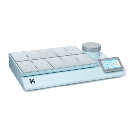
Product Overview Section 5 - Product Overview Main Components Components Incubator Chambers Touchscreen Preparation Chamber Origio Gas Line Filter G210 InviCell models - front view G210 InviCell models - raised top section... -
Page 17: Supplied Accessories For G210 Invicell Standard
Product Overview Components Product label Mains connection with fuse Ventilation holes Gas inlet connectors Alarm output Ethernet connector** **External computing devices connected to the Ethernet on the unit must only be Limited Power Source and SELV circuit according to the standards IEC/UL 60950-1. G210 InviCell Standard Model - back view On base of unit... -
Page 18: Accessory Order Codes
Product Overview Accessory Order Codes Order Code Description 23063-1 Falcon Dish Inserts 1 pc 23064-1 Nunc Dish Inserts 1 pc 22410-1 Nunc Dish Inserts 10 pc 23069 Vitrolife Dish Inserts 1 pc 23070-1 Vitrolife Dish Inserts 10 pc 22412-1 5 x Nunc Dish Inserts and 5 x Falcon Dish Inserts 23071-1 5 x Nunc Dish Inserts and 5 x Vitrolife Dish Inserts 23072-1... -
Page 19: Specification Table
Product Overview Specification Table Criteria Specification Overall dimensions, (L x W x H) 860mm x 550mm x 180mm Weight 53kg maximum Temperature range 35 – 42°C User interface Touchscreen Digital temperature readout, data logger, temperature User interface functions setpoint, calibration, warning for next service Connections Mains, CO gas, N... -
Page 20: Section 6 - G210 Invicell Plus
G210 InviCell Plus Section 6 - G210 InviCell Plus G210 InviCell Plus is not currently available for sale in the USA. -
Page 21: Section 7 - Set-Up
Set-up Section 7 - Set-up Before use, see chapter “Section 9 - Settings”. Gas Supply The G210 is not supplied sterile and should be cleaned before use. Make sure the gas input and output ports at the back of the incubator are also cleaned. See “Section 12 - Maintenance”... -
Page 22: Section 8 - Basic Operation
Basic Operation Section 8 - Basic Operation CAUTION: Do not use the incubator if the alarm system of the device has issued a failure message and the cause of the failure has not been corrected. It is important that the appropriate Dish Inserts are selected for the culture dishes used (Falcon, Nunc, Vitrolife) to ensure there is direct contact between the dish and the heated surface. -
Page 23: Main Menu
Basic Operation Main Menu Setpoint Settings Log Menu Calibration Service Alarm Advanced Date and View Time Main Menu The main screen provides an overview of the temperature and gas concentrations inside the incubator. Advanced Menu... -
Page 24: Chamber Information
Basic Operation Press Advanced (1) in the main menu. The advanced menu shows the temperature in each chamber. Chambers that are marked with blue (2) are occupied, chambers marked green (3) are vacant. To return to the main menu press Basic (4). Patient ID (5). -
Page 25: Log
Basic Operation The Log tab shows the temperature and gas concentration over a three hour period. Press the Flow/Press button (1) to see gas flow and pressure (see below image) over a three hour period. Press Level button (2) to return to temperature and gas concentration. -
Page 26: Changing The Temperature Setpoint
Basic Operation Enter your password and press OK (4). Changing the Temperature Setpoint Adjust the temperature setpoint by pressing the arrow buttons. Press Save (1). Changing the Gas Setpoint Adjust the gas setpoint by pressing the arrow buttons. Press Save (1) . It is recommended that gas concentrations are checked after changing the gas setpoint. -
Page 27: Section 9 - Settings
Settings Section 9 - Settings The Settings menu shows: Time settings (1) Date settings (2) Time format (3) Ethernet configuration (4) Security settings (5) System settings (6) Language (7) Basal Body Temperature (BBT) settings (8) To change some of these settings requires a login (see “Security Settings”... -
Page 28: Ethernet Settings
Settings Ethernet Settings Select the Configure button from the settings menu. We recommend allocating a static IP address to the device. However, you will need to consult with your IT department for network settings. Select DHCP (1), or Static IP (2) If static IP is selected, enter the settings provided by your IT department. -
Page 29: Security Settings
Settings Adjust the temperature T Max and T Min (4). When BBT is activated the temperature in the setpoint menu cannot be changed. Press one of the four time buttons (A, B, C or D). Adjust the time value by pressing the up and down arrows (5). -
Page 30: Access Levels
Settings Access Levels The unit supports three access levels: User, Administrator and Advanced User. Their characteristics are shown below: Advanced User Administrator User (login required) (login required) Changes that do not require login Change setpoint Change settings ... -
Page 31: Edit User
Settings Edit User Select a user in the Security window, and press Edit (1) . The access level, name and password can be edited here. Press Save (2) when done. Change Password Press Change password (1) to change the admin password. Enter the current password (2). -
Page 32: Create A New User
Settings Create a New User In the security window, press New (1). Delete User Select a user in the security window, and press Delete (1). It is not possible to delete the “admin” user. Confirm ‘OK’ to delete a user. Log Out In the Security window press Logout (1). -
Page 33: Alarm
Settings Alarm A flashing red light alarm button indicates that an alarm has been activated. An audible alarm will also be activated. Press the alarm button to open the alarm message box. The alarm box shows information about the current alarm. Press Mute (1) to turn off the audible alarm. -
Page 34: Section 10 - K-Link
K-Link Section 10 - K-Link K-Link software can be used to communicate with a G210 over a TCP/IP network to retrieve, display and save a log of measurements, warnings, and daily averages into a spreadsheet. K-Link can also be configured to send email notifications when alarms are triggered. Starting K-Link To launch the K-Link software, double click on the K-Link icon on the desktop or in the start menu. -
Page 35: Measurement Section
K-Link WARNING: Ensure that the system time of the computer running the K-Link software and the system time of the G210 have both been set to the correct time before proceeding. NOTE: To ensure a stable connection between K-Link and the G210, it is recommended that the G210 be configured with a static IP address. -
Page 36: Graph Section
K-Link Graph Section The graphs displayed will automatically scale to fit the measurements however the Y-Axis can be adjusted by holding down the left mouse button and “dragging” a box around an area of interest then releasing the button. A single left-click anywhere on the graph will reset to the original scale. Level Tab The Level tab displays a graph of the gas concentration levels over time. -
Page 37: Pressure Tab
K-Link Pressure Tab The Pressure tab displays a graph of the device measurements over time. Daily Average Tab The Daily Average tab displays daily averages for the individual measurements collected from the device every 24 hours. -
Page 38: Warning Tab
K-Link Warning Tab The Warning tab displays information about the last 50 individual alarms. Mail Tab The Mail tab allows users to configure K-Link to email notifications about alarms and service information. NOTE: It is recommended to configure K-Link to use your own mail server. Consult your IT Department for your mail server information. -
Page 39: Service Tab
K-Link Service Tab The service tab presents software version information, device connectivity and serial number information. It also shows counters to indicate when a general service check, a filter change should be conducted. When the counters time out, the service alarm light is triggered and will remain active until all counters are reset. -
Page 40: Section 11 - Troubleshooting
Troubleshooting Section 11 - Troubleshooting Heating System Symptom Cause Action The temperature is more than Wrong temperature The alarm is on 0.5°C off from the setpoint, wait for the temperature to stabilize Wrong temperature on The setpoint for temperature Check the desired temperature touchscreen after system has is wrong setpoint... -
Page 41: Gas Regulator
Troubleshooting Gas Regulator Symptom Cause Action System not powered on Check mains and main fuse gas regulator is off Activate O gas regulator No N or wrong gas type Check gas supply; make sure that Wrong O level measured at attached to N gas input 0.5-1.0 bar of N... -
Page 42: Section 12 - Maintenance
Maintenance Section 12 - Maintenance Periodic cleaning is recommended as part of routine maintenance. Disinfection is also recommended for media spills, visual accumulation of dust, and other evidence of contamination. Clean and disinfect the G210, and when necessary sterilize the Dish Inserts, immediately after any media spills. -
Page 43: Validation Check
Maintenance Validation Check Perform the following validation gas and temperature checks after all cleaning, disinfecting and sterilizing or at least every two weeks to ensure the G210 InviCell is operating correctly. Gas Calibration It is very important the the G210 is not emptied of gas during the gas calibration procedure. To do so will cause unstable gas levels and gas flow and will result in a considerable time before the gas concentration is recovered and becomes reliable and stable again. -
Page 44: Gas Sample Port
Maintenance Gas Sample Port The gas sample port is located behind the Preparation Chamber. The Gas Sample Port is connected directly to the gas-mixing chamber. Connect a length of tubing to the gas analyser input. Connect the coupler (K59688) from the supplied accessories to the tubing. Remove the protection cap from the sample port. -
Page 45: Chamber Lid Plug
Maintenance Chamber Lid Plug A silicone plug is placed in the lid of each chamber. For collecting a gas sample, penetrate the lid plug with a needle attached to tubing and connect to the gas analyser input. Do not use needles larger than 0.5 mm x 25 mm. -
Page 46: Temperature Calibration
We recommend the F100 Precision Thermometer together with the Solid Temperature Sensor for temperature calibration. If the calibration is not performed with the K-Systems Solid Temperature Sensor, CooperSurgical cannot guarantee correct calibration of the device. NOTE: The sensor and thermometer should be calibrated as a unit and only by an accredited test house. -
Page 47: Section 13 - Service
Service Section 13 - Service WARNING: DO NOT disassemble or modify any part of the G210 InviCell For the reliable and safe operation of this incubator it is strongly recommended that inspections and services are performed as stated in the Service Plan below. Failing to follow this plan may cause the unit to stop performing as intended and cause damage to embryos, blastocysts etc. -
Page 48: Replacing The Origio Gas Line Filter
Service Replacing the Origio Gas Line Filter Remove all samples from the chambers before replacing the filters. To access to the filter compartment, push the safety lock lever (1) and lift the upper part of the incubator containing the chambers. Fasten the connectors to the inlet and outlet of the Origio Gas Line Filter (2). -
Page 49: Section 14 - Disposal And Recycling
If any electronic component is no longer serviceable, it must be sent back to CooperSurgical to be destroyed in an environmentally safe way. Do not dispose of with ‘normal’ waste. The following table provides information on the recycling and handling of the product in accordance... -
Page 50: Section 15 - Warranty Information And Limits On Liability
Coopersurgical Inc, warrants that this item will be free from defects in materials and workmanship for one year from the date of installation. If Coopersurgical (CSI) determines that the product fails to conform to that warranty during the one-year period, CSI will repair or replace the product, at CSI’s discretion, free of charge. - Page 51 Returning Product to CSI for Repair Section 16 - Returning Product to CSI for Repair Please refer to the ‘Troubleshooting’ section in this manual before returning product to CSI. If you continue to have a problem with your device, please follow these instructions: Returned Goods Policy Goods will be accepted for return for the following reasons: •...
- Page 52 Returning Product to CSI for Repair Customer Service Contact Details: Tel: +45 46 79 02 02 Fax: +45 46 79 03 02 E-mail: customerservice@origio.com Coopersurgical.com US Only Customers Contact Details: Tel: 800-243-2974 Fax: 800-262-0105 Coopersurgical.com...
Need help?
Do you have a question about the K-Systems G210 InviCell and is the answer not in the manual?
Questions and answers