Table of Contents
Advertisement
Quick Links
Advertisement
Table of Contents

Related Manuals for Spectrum Technologies WatchDog Cellular Alert Standard


Summary of Contents for Spectrum Technologies WatchDog Cellular Alert Standard
- Page 1 ® Cellular Alert Standard PRODUCT MANUAL Item #3450...
-
Page 2: Table Of Contents
WatchDog Cellular Alert. Please read this manual thoroughly before using your instrument. For customer support, or to place an order, call Spectrum Technologies, Inc. at 800-248- 8873 or 815-436-4440 between 7:30 am and 5:30 p.m. CST, FAX at 815-436-4460, or E-Mail at info@specmeters.com. -
Page 3: General Overview
General Overview Thank you for purchasing a WatchDog Cellular Alert. This manual describes how to use your WatchDog Cellular Alert and how to keep it working accurately for many years. This manual will describe how to use the standard version which is used with a cell phone. -
Page 4: Specifications
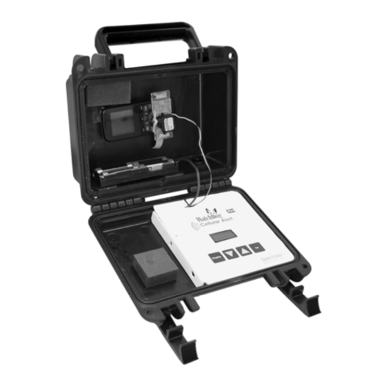
Specifications Hard Case with Handle—8 3/4” x 7” x 4” deep LED Light—flashing green and red Hole with gland nut for external sensor cables Relay switch External Temperature Sensor Control Panel with LCD display Battery Compartment U-Bolt (used for mounting) Tie Strap (1) Mounting Plate Velcro (2) -
Page 5: Standard Model Setup
Standard Model Set Up The standard model is designed to dial a pre programmed number or the last dialed number on the cell phone (not included). Please refer to your phone manual to set up the number to be dialed. Phone Set Up—To view set up video visit www.specmeters.com Position mounting plate on phone to determine which slots on either end should be used for weaving the tie strap. - Page 6 Standard Model Set Up Secure mounting plate to phone. See pictures below. The secure mounting plate should resemble the following picture. Again ensure the plate is in the correct position by pressing on the sides of the mounting plate and verifying the mounting plate is not pressing on the buttons.
- Page 7 Standard Model Set Up Attach the actuator to the mounting plate so the arm lines up with Installation and the ‘talk’ or speed dial button. The actuator should snap into the mounting plate. Test that the actuator is lined up properly by Placement pushing down the arm gently and having it touch the button.
- Page 8 Standard model set up Battery Setup Place the batteries into the battery pack. Once batteries are in properly, the LCD display will light up (for 30 seconds and turn off automatically). Alert Testing Actuator To test the actuator, after plugging the actuator cable into the control panel board, press the DISPLAY button on the control panel until it reads ‘TEST’.
- Page 9 Sensor set up Sensor Setup Take the cable of the temperature sensor and run the sensor plug into the box through the gland nut, then through the wire hook. Tighten the gland nut once the cable is positioned. Plug the temperature sensor into the side of the control panel. WIRE HOOK...
-
Page 10: Programming Control Panel-Standard
Programming Control Panel—Standard The DISPLAY button is used to toggle between the various modes. These modes are Off, Test, Setup, Run. Once the desired mode is displayed press the SET button. Off Mode—Turns the cellular alert off—Cancels Run Mode. Test Mode—Used to test the alert function. When the Test Mode is chosen, the LCD display will show diagnosis and status information. - Page 11 Programming Control Panel—Standard Limit (continued) The Alert will monitor a value either crossing above or below a threshold. Select above or below using the up and down arrow buttons, then SET to select your choice. The display will toggle to allow you to set the threshold value.
-
Page 12: Relay Function Setup
Relay Function SETUP The Cellular Alert has a relay that may be used to trigger an ac- tion with the alert such as, turn on a fan or turn on an irrigation system. This action will result when the sensor crosses above or below the threshold that was determined when programming the control panel. -
Page 13: Led Light Definition
LED Light Definition There is an LED light that shows through the outside of the case. The light indicates what mode the cellular alert is in. The following chart shows the patterns: Light Pattern Mode Short green flash each 5 sec- Run mode, sensor in normal onds range... -
Page 14: Repositioning Actuator Arm
Repositioning Actuator Arm If, after assembling the actuator to the phone, the arm does not rotate enough to depress the phone button, the arm should be repositioned on the actuator hub. Note the position of the actuator after Test mode has been used. Disassemble the arm from the actuator by removing the center screw and pulling the arm off. - Page 15 Repositioning Actuator Arm Reassemble the arm by repositioning the arm rotated clockwise one tooth. Reassemble the actuator assembly to the phone and re-test. troubleshooting The firmware version number will appear on the LCD screen when the module is first activated.
-
Page 16: Warranty
Warranty This product is warranted to be free from defects in material or work- manship for one year from the date of purchase. During the warranty period Spectrum will, at its option, either repair or replace products that prove to be defective. This warranty does not cover damage due to improper installation or use, lightning, negligence, accident, or unau- thorized modifications, or to incidental or consequential damages be- yond the Spectrum product.
Need help?
Do you have a question about the WatchDog Cellular Alert Standard and is the answer not in the manual?
Questions and answers