
Summary of Contents for PDi RF-HEMiS PD890-1009
- Page 1 USER MANUAL Document Number: PD196-391R3 RF-HEMiS ™ Head-end Management Integrated TV Server PD890-1009 mymedTV.com...
-
Page 2: Table Of Contents
Add Update Menu....................................9 Broadcast Settings Menu ................................10 Edit Groups Menu ................................... 11 SUPPORT INFORMATION ..................................12 LIMITED WARRANTY ....................................12 SPECIFICATIONS......................................13 www.pdiarm.com www.mymedTV.com PDi Communication Systems, Inc. ▪ 40 Greenwood Ln ▪ Springboro, Ohio 45066 USA ▪ ▪ Phone 800.628.9870... -
Page 3: Overview
Page 3 of 13 OVERVIEW The PDi RF-HEMiS allows all the TVs in the building to be upgraded together, from the head end. It does this by inserting upgrade information into the building’s RF coax cable plant. Compatible TVs include PDi A-series, E- series, medTV and medTAB products. -
Page 4: Operation
TV user manual. Enabling RF Updating Refer to the TV user manual for instructions on how to enable the RF-HEMiS on your PDi TVs. RF-HEMiS INSTALLATION Follow these steps for initial installation. A LAN connection is optional. -
Page 5: Security
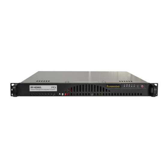
MAINTENANCE The PDi RF-HEMiS is designed to run continuously in a standard 19” rack. As with any server, it will provide years of service if the chassis is periodically cleared of dust. The internal chassis fan is the only moving part. The RF- HEMiS is based on a Supermicro SYS-5018A-MLTN4 server. -
Page 6: Initial Rf Clone Manager App Configuration
To make use of the RF Clone Manager app, at least one TDF is required. Settings TDFs are generated by television sets and saved to a USB flash drive (see your TV user manual for details). (Firmware TDF’s are provided by PDi). -
Page 7: Creating An Update
User Manual Page 7 of 13 or stretch) splash images. To ensure optimal image quality, refer to the PDi TV user manual to check the splash image resolution requirement. The sizes are typically either 1920x1080 or 1366x768. Images should be sized accordingly prior to loading into the RF Clone Manager App. -
Page 8: Rf Clone Manager App Reference
The Main Screen of the RF Clone Manager app allows access to all other parts of the app via the menu bar along the top. It also is home to the Saved Update List and is where broadcasts are started and stopped. www.pdiarm.com www.mymedTV.com PDi Communication Systems, Inc. ▪ 40 Greenwood Ln ▪ Springboro, Ohio 45066 USA ▪ ▪ Phone 800.628.9870... -
Page 9: Add Update Menu
“Add TDF” button. Additionally, JPEG splash images can be added to updates via the “Add JPEG Button”. To save these update settings, an Update Name and at least one TDF file is required. www.pdiarm.com www.mymedTV.com PDi Communication Systems, Inc. ▪ 40 Greenwood Ln ▪ Springboro, Ohio 45066 USA ▪ ▪ Phone 800.628.9870... -
Page 10: Broadcast Settings Menu
The Broadcast Settings Menu allows the user to adjust the RF broadcast settings. Channel type/number defaults to Cable 2 on all PDi Televisions and in the Application. NOTE: It needs to be changed here, and on each TV, if channel 2 is already being used for TV programming. -
Page 11: Edit Groups Menu
2. Custom Label Field: Text entry space for custom labels. This allows you to associate the predefined group IDs with names meaningful to you. www.pdiarm.com www.mymedTV.com PDi Communication Systems, Inc. ▪ 40 Greenwood Ln ▪ Springboro, Ohio 45066 USA ▪ ▪ Phone 800.628.9870... -
Page 12: Support Information
800.628.9870 LIMITED WARRANTY PDi Communication Systems Inc., (“PDi”) standard warranty information is found at pdiarm.com. For information regarding authorized servicing and all other information pertaining to this warranty, please contact PDi COMMUNICATION SYSTEMS, INC. at 40 Greenwood Ln, Springboro, Ohio 45066 or phone 800-628-9870 and ask for the PDi ProServices team. -
Page 13: Specifications
QAM or 8VSB Connector 75Ω F-female Physical Rack dimension 1U x 14" deep Power Input 100V-240V 3A-1.5A Typical Power Consumption 30 W www.pdiarm.com www.mymedTV.com PDi Communication Systems, Inc. ▪ 40 Greenwood Ln ▪ Springboro, Ohio 45066 USA ▪ ▪ Phone 800.628.9870...
Need help?
Do you have a question about the RF-HEMiS PD890-1009 and is the answer not in the manual?
Questions and answers