Table of Contents
Advertisement
Quick Links
Advertisement
Table of Contents

Subscribe to Our Youtube Channel
Summary of Contents for StoneAge NAV-100
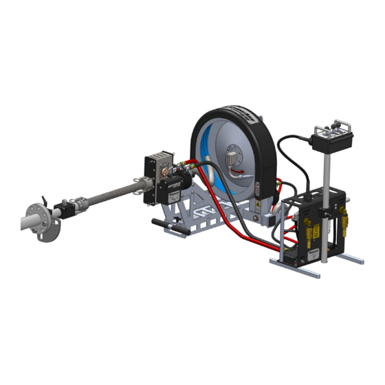
- Page 1 NAVIGATOR (NAV-100) & CONTROL BOX (CB-NAV) USER MANUAL PL 613 REV G (10/2019)
-
Page 2: Table Of Contents
..............NAVIGATOR (NAV-100) SET-UP . -
Page 3: Manufacturer's Information
Modular, lightweight design • The Navigator NAV-100 mounts to pipes from 2 inches (51 mm) to 4 Quick install • inches (102 mm) in diameter. The Navigator NAV-100 will... - Page 4 EN ISO 12100:2010 (E) Safety of machinery – General principles for design – Risk assessment and risk reduction The Technical File for Navigator (NAV-100) and Control Box (CBX-NAV) is maintained at: StoneAge Incorporated, 466 South Skylane Drive, Durango, CO 81303, USA and was compiled by the Engineering Manager. The Technical File is available through the Authorized Representative.
- Page 5 NOTES This page is intentionally left blank. 866-795-1586 • WWW.STONEAGETOOLS.COM...
-
Page 6: Warning And Safety Instructions
Aerosols • StoneAge WILL NOT accept responsibility for the results of misuse. Biological and microbiological (viral or bacterial) agents • IT IS THE RESPONSIBILITY OF THE INSTALLER/OPERATOR Combustible materials •... -
Page 7: Pre-Run Safety Check
Operator has good visibility of the pipe and hose. The Navigator Ensure that Operators never connect, disconnect, or tighten • NAV-100 and Control Box MUST be supervised at all times and hoses, adapters, or accessories with the high-pressure water should never be left unattended. -
Page 8: System Assembly - Overview
SYSTEM ASSEMBLY - OVERVIEW NAVIGATOR PIPE ATTACHMENT AND BACKOUT PREVENTION ASSEMBLIES RECOMMENDED COLLET SIZES ARE LOCATED IN THE “PART DIAGRAM“ SECTION AT THE BACK OF THIS MANUAL FF-121-XXX BOP 084 BOP 081-6 COLLET THREADED SNOUT TUBE SNOUT TUBE SNOUT BOP 090 Pipe shown for graphic representation only. - Page 9 SYSTEM ASSEMBLY - OVERVIEW NAVIGATOR WITH CONTROL BOX ASSEMBLY (NAV-100 AND CB-NAV) DRUM FRAME ASSEMBLY ABX-PRO TRACTOR ASSEMBLY ELBOW ADJUSTABLE HEIGHT STAND 18 IN -28 IN 457mm - 711mm BASE FRAME ASSEMBLY FORWARD AND REVERSE REMOTE SPEED CONTROLS CONTROL BOX...
-
Page 10: Navigator (Nav-100) Set-Up
NAVIGATOR SET-UP HOSE DRUM ASSEMBLY TO BASE FRAME ASSEMBLY Remove Quick Release Pin from Base Frame Assembly. Install the Hose Drum Assembly onto the Base Frame Assembly by placing the shoulder screw heads into the notches on the Joint Plates and inserting the Quick Release Pin through the holes in the Joint Plates. - Page 11 NAVIGATOR SET-UP ABX-PRO PRODRIVE TO BASE FRAME ASSEMBLY Remove Quick Release Pin from Base Frame Assembly, Install the ABX-PRO PRODRIVE onto the Base Frame Assembly by sliding the Guide Tube into the Drive Mounting Block and inserting the Quick Release Pin. (Figure 2) GUIDE TUBE DRIVE MOUNTING...
- Page 12 NAVIGATOR SET-UP LOADING THE HIGH-PRESSURE HOSE NOTICE Only high quality hoses intended for waterblast applications should be used as high-pressure hoses. Pressure rating of high-pressure hoses MUST NEVER be exceeded. Do not use a shrouded hose or hose with a steel protective cover. This will cause severe damage to the Rollers. Connect the female hose end to the hose connection tube and wind the hose in the direction of the arrow inside the drum.
- Page 13 NAVIGATOR SET-UP 3. With the Rollers open, slip the hose through the Drive Block, Rollers and Guide Tube. Be sure to pull enough extension to feed through the Snout. (Figure 3) DRIVE MALE BLOCK HOSE GUIDE TUBE ROLLERS FIGURE 3 Rotate the Cam Lever clockwise to the “Engaged”...
- Page 14 NAVIGATOR SET-UP SNOUT ASSEMBLY TO ABX-PRO PRODRIVE 1. Pull on the Camlock Release Rings and slide the Camlock onto the male end of the ABX-PRO PRODRIVE. Push the Camlock pins back to lock into place. (Figure 1) Pull on the Snout Assembly to make sure it is secured. Feed the rest of the hose through the Snout Assembly and leave enough length to feed through a pipe flange attachment.
- Page 15 QUARTER PLATE FLANGE MOUNT ASSEMBLY SET-UP - INCLUDED SNOUT CONNECTION AND BACKOUT PREVENTION ASSEMBLY Thread the BOP 084 Threaded Snout Tube into the BOP 085 Camlock at the end of the BOP 090 Snout. (Figure 3) SNOUT BOP 084 BOP 090 THREADED SNOUT TUBE BOP 085...
-
Page 16: Quarter Plate Flange Mount Set-Up
NOTICE The NAVIGATOR NAV-100 comes with one customer specified FF 121-XXX Collet installed in the BOP 030 Collet Block Assembly. It is necessary to change the Collet size when changing to a different diameter hose. There are additional roller and collet sizes beyond the list below that are only to be used when operating the ABX-PRO as part of the ABX-PRO-100 PRODRIVE Assembly. -
Page 17: Strap Mount Assembly Set-Up- Optional
STRAP MOUNT ASSEMBLY SET-UP- OPTIONAL STRAP MOUNT ASSEMBLY (BOP 050) - MALE POSITIONER SIDE The Strap Mount Assembly (BOP 050) is designed for pipes that do not have flanges. Attach the strap end to the strap capture bar and wrap the strap around the pipe towards the Winch Assembly. (Figure 1) WINCH ASSEMBLY STRAP END TO... - Page 18 STRAP MOUNT ASSEMBLY SET-UP- OPTIONAL STRAP MOUNT ASSEMBLY (BOP 050) - FEMALE POSITIONER SIDE Release the Adjustable Handle on the BOP 070 Hinge Clamp to access the 4 socket head cap screws. Locate the side of the BOP 030 Collet Block Assembly with 4 threaded holes. Orient the Hinge Clamp so that the hinge is on the right. Fasten the Hinge Clamp Assembly to the Collet Block Assembly using the 4 supplied socket head cap screws.
- Page 19 NOTICE The NAVIGATOR NAV-100 comes with one customer specified FF 121-XXX Collet installed in the BOP 030 Collet Block Assembly. It is necessary to change the Collet size when changing to a different diameter hose. There are additional roller and collet sizes beyond the list below that are only to be used when operating the ABX-PRO as part of the ABX-PRO-100 PRODRIVE Assembly.
-
Page 20: Tight Pipe Flange Joint Attachment Options
TIGHT PIPE FLANGE JOINT ATTACHMENT OPTIONS NAV-100 NAVIGATOR ASSEMBLY WITH STRAIGHT MOUNTING OPTIONS *THE MOUNTING OPTION BELOW IS USED ON FLANGED PIPES* (INCLUDED WITH NAVIGATOR PACKAGE) QUARTER PLATE BOP Pipe shown for graphic BOP 010-2-4 QTR representation only. Not included in assembly. - Page 21 FOR 45o BENDS. A STANDARD 1.75” ELECTRICAL CONDUIT CAN ALSO BE USED FOR CONNECTIONS OF VARYING ANGLES. MAINTAIN A GREATER THAN 6” CENTERLINE RADIUS BEND TO AVOID CONSTRAINING THE MOVEMENT OF THE TOOL. NAV-100 NAVIGATOR ASSEMBLY WITH QUARTER PLATE MOUNT *OPTIONAL* BOP 082-9-45 45°...
-
Page 22: Control Box Set-Up
CONTROL BOX SET-UP PNEUMATIC AIR LINE CONNECTIONS Pull the Dust Caps off the Pneumatic Air Fittings on the control box and the air motors. 2. Connect the 1/2” Pneumatic Supply Lines from the Control Box to the ProDrive Assembly. (Figure 1) 3. - Page 23 CONTROL BOX SET-UP AIR SUPPLY AND LUBRICATOR SETTING The CB-NAV Control Box is supplied with a twist claw style inlet coupling (Chicago style) located on the side of the FRL Assembly. Connect a compatible compressed air line (not included) according to the Manufacturer’s instructions. Using the pressure regulator on the FRL, adjust the operating pressure to 100 psi (0.7 MPa) for the application.
-
Page 24: Operation
Use mild soapy water to clean the machine in order to remove corrosive materials. The Navigator (NAV-100) can be easily transported by lifting the handle on the base assembly and wheeling it to its next location. -
Page 25: Maintenance And Troubleshooting
-Tighten eccentric lever to retain clamp force on hose. -Check Rollers for excessive wear in groove Contact StoneAge for Safety Data Sheets for material usage, a complete list of spare part numbers, and service instructions for the Navigator (NAV-100), ProDrive (ABX-PRO), and Control Box (CB-NAV). -
Page 26: Roller Removal Instructions
ROLLER REMOVAL INSTRUCTIONS ROLLER REMOVAL NOTICE This process will be typical for Poly Roller replacements on the ABX-PRO Tractor Assembly. Installation of the appropriate Roller should be completed prior to installing the hose and tool into the AUTOBOX® ProDrive ABX-PRO-100 Assembly. WARNING Always de-energize the system before servicing or replacing any parts. -
Page 27: Roller Installation Instructions
ROLLER INSTALLATION INSTRUCTIONS ROLLER INSTALLATION NOTICE This process will be typical for Poly Roller replacements on for the ABX-PRO Tractor Assembly. Installation of the appropriate Roller should be completed prior to installing the hose and tool into the AUTOBOX® ProDrive ABX-PRO-100 Assembly. WARNING Always de-energize the system before servicing or replacing any parts. - Page 28 PARTS DIAGRAM NAVIGATOR (NAV-100) FULL ASSEMBLY PART NUMBER QTY. LINE ITEM ACCESSORIES FOR THE NAVIGATOR: ABX-PRO AUTOBOX PRODRIVE TRACTOR ASSEMBLY CONTROL BOX, PN: CB-NAV BOP 010-2-4-QTR QUARTER PLATE BOP COLLET (BASED ON HOSE SIZE), PN: FF 121-XXX BOP 030 COLLET BLOCK ASSEMBLY HIGH PRESSURE WATER HOSE, 9/16-18 TYPE M FEMALE SWIVEL (4/4, 5/4 or 6/4) BOP 081-6 SNOUT TUBE 1.75 X 6 SS...
- Page 29 PARTS DIAGRAM NAVIGATOR (NAV 110) BASE FRAME ASSEMBLY NOTE: 1. APPLY THREAD ADHESIVE TO ALL THREADED COMPONENTS BLUE LOCTITE: PN: 242 OR EQUIVALENT. 2. APPLY GREEN RETAINING COMPOUND, LOCTITE PN: 290 OR EQUIVALENT TO COMPONENTS AS NOTED. 3. ASSURE INSIDE OF GRIP AND OUTER SURFACE OF ALUMINUM BAR ARE FREE OF GREASE, OILS, AND DIRT. COAT THE INSIDE OF THE GRIP AND OUTSIDE OF THE ALUMINUM BAR WITH ISOPROPYL ALCOHOL, THEN SLIDE GRIP FULLY ONTO ALUMINUM BAR TO INSTALL.
- Page 30 PARTS DIAGRAM NAVIGATOR (NAV 130) DRUM FRAME ASSEMBLY SHEET 1 (CONTINUED ON NEXT PAGE) NOTE: 1. SWIVEL, FLANGE, DRUM, ELBOW & LOCKING PLATE INSTALLATION: a) SECURE SWIVEL WITHIN CLAMPS AT LOCATION SHOWN IN TOP VIEW. b) SLIDE ADAPTER FLANGE FULLY ONTO SWIVEL SHAFT (PROFILED SIDE TOWARD SWIVEL), ALIGN SCREW WITH FLAT ON SWIVEL SHAFT AS NOTED, THEN TIGHTEN BOTH SCREWS SECURELY (USE BLUE GOOP).
- Page 31 PARTS DIAGRAM NAVIGATOR (NAV 130) DRUM FRAME ASSEMBLY SHEET 2 SEE SEPARATE MANUAL INSERT, INCLUDED IN THE PACKAGE FOR DETAILS ON SWIVEL PARTS AND MAINTENANCE PART NUMBER SG-MP12K-62-90 SWIVEL HCS 103 DRUM ADAPTER FLANGE AF 063-MP12 ADAPTER, 3/4 MP MALE X 1 TYPE M MALE HCS 105 KMP9 ELBOW AF 070-MP9 GLAND, 9/16 MEDIUM PRESSURE HCS 120 ELBOW LOCKING PLATE...
- Page 32 PARTS DIAGRAM AUTOBOX PRODRIVE (ABX-PRO) ® TRACTOR ASSEMBLY NOTE: 1. ADD 5.0 OUNCES OF MOBIL SYNTHETIC OIL SCH 634 (SA# GP 146.1) 2. THIS WORM CAP WILL BOTTOM ON BEARING, WILL NOT BOTTOM ON HOUSING WHEN TIGHTENED 3. ADD PRELUBE TO ALL SHAFTS, GEARS, BEARINGS, AND SEALS. 4.
- Page 33 COLLET STOPS The NAVIGATOR NAV-100 comes with one customer specified FF 121-XXX Collet installed in the BOP 030 Collet Block Assembly. It is necessary to change the Collet size when changing to a different diameter hose. There are additional roller and collet sizes beyond the list below that are only to be used when operating the ABX-PRO as part of the ABX-PRO-100 PRODRIVE Assembly.
- Page 34 PARTS DIAGRAM BOP 030 COLLET BLOCK ASSEMBLY NOTE: 1. ADD BLUE GOOP (A SWAGELOK BRAND) ANTI-SEIZE. TO ALL THREADED HARDWARE. AN EQUIVALENT ALTERNATIVE IS ACCEPTABLE. 2. BLUE LOCTITE PN: 242 OR EQUIVALENT PART NUMBER QTY. BOP 031 COLLET BLOCK BODY BOP 032 COLLET BLOCK CAP BOP 033 QUICK PIN GS 331-06 SHCS .31-18 x 1.50 SS...
- Page 35 PARTS DIAGRAM PRODRIVE (PRO 170) IDLER ROLLER ASSEMBLY NOTE: 1. 5x BLUE LOCTITE: PN: 242 OR EQUIVALENT 2. APPLY BLUE GOOP (A SWAGELOK BRAND) ANTI-SEIZE. PART NUMBER QTY. PRO 180 RETAINING RING PRO 174-46 POLY ROLLER PRO 176 IDLER SHAFT GSF 319-02-24 FHCS .19-24 X .50 PRO 173 ROLLER PLATE LG SS...
- Page 36 PARTS DIAGRAM NAVIGATOR (CB-NAV) CONTROL BOX ASSEMBLY NOTE: 1. BLUE LOCTITE: PN: 242 OR EQUIVALENT 2. APPLY BLUE GOOP (A SWAGELOK BRAND) ANTI-SEIZE. PART NUMBER QTY. CB 732 FTG TUBE STEM WYE, PL2 CB 700 NAVIGATOR REMOTE BOX CB 747 RIVET 1-8 X .25 CB 705 FRL VALVE COVER GN 319-L NYLOK NUT SS (HC 025.1) CB 710 OR VALVE...
- Page 37 PARTS DIAGRAM NAVIGATOR (CB 700) REMOTE BOX PART NUMBER QTY. CB 724 MODIFIED COLLAR CB 708 ENCLOSURE NAVIGATOR CB 725 THREAD LOCKING SLOTTED INSERT CB 709 GRAPHIC NAVIGATOR CB 726 THREE LOBE KNOB, .25-20 CB 710 OR VALVE CB 728 Spacer, .192ID .313OD .75Lg CB 713 CRIMP RUNG GN 519-L-32 NYLOK NUT CB 714 CORD GRIP, .51-.79...
- Page 38 PARTS DIAGRAM NAVIGATOR (CB 730) FRL BASE ASSEMBLY NOTE: 1. APPLY BLUE GOOP (A SWAGELOK BRAND) ANTI-SEIZE. 2. ADD BLUE LOCTITE: PN: 242 OR EQUIVALENT TO ALL THREADED HARDWARE. 3. ADD LOCTITE THREAD SEALANT 567 TO ALL NPT THREADS. AN EQUIVALENT ALTERNATIVE IS ACCEPTABLE 4.
-
Page 39: Part Diagrams
PART DIAGRAM NAVIGATOR (CB 720) GEN 3 FILTER, REGULATOR, LUBRICATOR WITH GEN 2 CLAMP WITH AIR TAP PART NUMBER QTY. CB 312.1 GEN3 REGULATOR-FILTER CB 312.2 LUBRICATOR AL40-N04-Z-A CB 312.3 SPACER W BRACKET, GEN2 Y400T CB 312.4 SPACER ATTACHMENT Y410-N02-A CB 312.5 SPACER WITHOUT BRACKET, GEN2 Y400 CB 312.1.4 LENS COVER FOR GAUGE CB 312.1.6 FILTER... - Page 40 NOTES This page is intentionally left blank. 866-795-1586 • WWW.STONEAGETOOLS.COM...
- Page 41 NOTES This page is intentionally left blank. 866-795-1586 • WWW.STONEAGETOOLS.COM...
-
Page 42: Terms And Conditions
Conditions of Sale (“Terms and Conditions”) shall operate as the acceptance of these Terms and Conditions at any time, shall not in any way affect, limit or by StoneAge, Inc. (“Seller”) of the order submitted by the purchaser (“Buyer”). waive Seller’s right thereafter to enforce and compel strict compliance with Such acceptance is made expressly conditional on assent by Buyer to these every term and condition hereof. - Page 43 Product EXTENT SUCH DAMAGES WOULD CONSTITUTE DIRECT DAMAGES), WITH at any time without notice to End-User, and StoneAge is not obligated to make RESPECT TO THE COVERED STONEAGE PRODUCT, OR OTHERWISE...
- Page 44 1-866-795-1586 • www.STONEAGETOOLS.com © 2019 StoneAge, Inc. All Rights Reserved...
Need help?
Do you have a question about the NAV-100 and is the answer not in the manual?
Questions and answers