Table of Contents
Advertisement
Quick Links
Advertisement
Table of Contents

Summary of Contents for Lenord+Bauer GEL 104
- Page 1 Artisan Technology Group is your source for quality new and certified-used/pre-owned equipment SERVICE CENTER REPAIRS WE BUY USED EQUIPMENT • FAST SHIPPING AND DELIVERY Experienced engineers and technicians on staff Sell your excess, underutilized, and idle used equipment at our full-service, in-house repair center We also offer credit for buy-backs and trade-ins •...
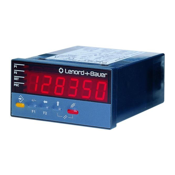
- Page 2 Programmable Preselect Counter GEL 104 User Manual © & C H, 04/99 Subject to change without notice ENORD AUER MO T O R T E C H N O L O G Y L T D TELEPHONE: +44 (0)161 217 7100...
- Page 3 Lenord, Bauer & Co. GmbH Dohlenstraße 32 D - 46 145 Oberhausen Phone +49 - 208 - 99 63 - 0 • Fax +49 - 208 - 67 62 92 Internet: http://www.lenord.de • E-Mail: info@lenord.de...
-
Page 4: Table Of Contents
G E L 1 0 4 P E R A T O R A N U A L C o n t e n t s 1 Introduction ....................1 Fundamental safety instructions.............1 Designated use ..................2 Guarantee, liability and copyright ............2 2 Control elements.................. -
Page 6: Introduction
NTRODUCTION 1 Introduction 1.1 Fundamental safety instructions The programmable preselect counters type GEL 104 have been built in accordance with state-of-the-art standards and the recognised safety regulations. Nevertheless, its use may constitute a risk to life and limb of the user or of third parties, or cause damage to the counter or to other compo- nents property. -
Page 7: Designated Use
NTRODUCTION 1.2 Designated use The GEL 104-type counters have been exclusively built for measuring and controlling purposes in industry. In conjunction with an incremental pulse generator, e.g. positions, lengths or angles may be measured and displayed or cutting and dosing jobs may be performed. -
Page 8: Control Elements
ONTROL ELEMENTS 2 Control elements 2.1 Keyboard The function of these five keys depends on the current mode of operation of the counter. X1104055 store key • in counting mode: in conjunction with another key only: start programming mode (see further below) •... -
Page 9: Display
ONTROL ELEMENTS cursor key 'up' • when switching on: together with the store key: activate system programming mode • in counting mode: together with the delete key: reset = set count to set value and reset outputs ( + • in programming mode: increment value at active input position delete key •... -
Page 10: Programming
ROGRAMMING 3 Programming Several programming planes are available for programming the counter. Via the 1st programming plane the user is provided with access to the operating parameters, i.e. preselection 1 / 2 and set value, which are frequently changed. In the second programming plane the display parameters, the prescaler and the decimal point can be set. -
Page 11: Preselections 1 (P1) And 2 (P2)
ROGRAMMING 3.1.1 Preselections 1 (P1) and 2 (P2) Key: for preselection 1 (P1) for preselection 2 (P2) P1 may be interpreted either as absolute or relative value (see para. 3.3, system parameter F20). P2 is the main preselection by means of which an automatic reset is initiated in the counter, provided that it had been programmed accordingly (see para. -
Page 12: Decimal Point
ROGRAMMING Setting range: 0.0005 … 99.9999 (standard setting: 1.0000) If you enter a value less than 0.0005 the error message Error0 will be emitted. To enter a new value press the store key. 3.2.2 Decimal point Use the cursor key to select one of the 4 possible variants: = display without decimal point –... - Page 13 ROGRAMMING phase discriminator mode with edge evaluation once, twice, quadruple Input A 90° Input B 0° Count eval.: x4 eval.: x2 eval.: x1 down E110401C 2. Input frequency input damping 0.03 30 Hz (bounce-proof), 40 kHz 3. Mode count = P2 ⇒ no automatic reset automatic reset 4.
- Page 14 ROGRAMMING 8. Output signal memory outputs reset after having switched on the power supply same switching status as prior to switching on the power supply, monostable times, however, being started anew 9. Input signal level npn: active level: Low pnp: active level: High 10.
-
Page 15: Control Signals
ONTROL SIGNALS 4 Control signals 4.1 Count inputs Input A and Input B The count inputs (terminals 30 and 29) are controlled with the positive or negative signal edge (pnp / npn, see system parameter F24). The maximum counter frequency is 40 kHz. You may use all commercial electronic pulse generators, whose High level is >... -
Page 16: Display Hold
ONTROL SIGNALS parameter F24). Thus you can interrupt the counting mode, although the counting pulses continue. 4.4 Display Hold As long as High (or Low) level is applied to the control input Hold (terminal 27), the current count of the counter is 'frozen' without loosing any pulse (the active level is fixed by system parameter F24);... - Page 17 ONTROL SIGNALS 1. Monostable outputs a) without automatic reset Count Out 2 E110401D b) with automatic reset (negative set value) Count Out 1 Out 2 E110401E 2. Bistable outputs Count Out 1 Out 2 Reset E110401F...
-
Page 18: Assembly, Commissioning, Diagnosis Of Errors
SSEMBLY COMMISSIONING DIAGNOSIS OF ERRORS 5 Assembly, commissioning, diagnosis of errors 5.1 Assembly instructions 1. Before incorporating the counter into the control panel the installation frame (see dimensioned drawing in chapter 6) must be pulled off the counter housing. For this purpose slightly lift the 4 catch brackets (alternately on top and at the bottom, and pushing them forward catch by catch). -
Page 19: Diagnosis Of Errors
SSEMBLY COMMISSIONING DIAGNOSIS OF ERRORS 5.3 Diagnosis of errors Problem Possible cause • supply voltage OFF or improperly connected no display • short-time: self-test after having switched on all display segments are ON the supply voltage • sporadic: contact of supply voltage connections not in perfect condition or voltage fluctuates under the minimum value •... -
Page 20: Technical Specification
ECHNICAL SPECIFICATION 6 Technical specification 6.1 Mechanical data dimensions (W × H × D) 96 × 48 × 108 mm (acc. to DIN 43 700) fastening in the panel cut-out 92 × 45 mm with clamping frame, screws M3 control panel thickness max. - Page 21 ECHNICAL SPECIFICATION peak current consumption max. 300 mA (incl. 60 mA encoder current) power consumption max. 4.5 W (worst case) b) AC 115 / 230 VAC -10% / +6%, 50…60 Hz overload protection external fuse: 115 VAC : 63 mA slow-blow 230 VAC : 32 mA slow-blow current consumption typ.
-
Page 22: Environmental Conditions
(DIN 40 040) 40°C / 92% relative humidity of air contamination level 2 acc. to VDE 0110 6.4 Type code GEL 104.1 DC operating voltage 12 ... 24 VDC GEL 104.2 AC operating voltage 115 / 230 VAC... -
Page 23: Dimensions
ECHNICAL SPECIFICATION 6.5 Dimensions plug-in clamping frame terminals Panel Cutout E1104084... -
Page 24: Pin Layout
IN LAYOUT 7 Pin layout DC version AC version 0.25 A F (12 V), 0.16 A T (24 V) IEC 127 32 mA T 63 mA T 0.25 A T (12 V), 0.20 A T (24 V) UL 198 : 12...24 V= [m]A T: slow-blow [m]A F: fast-blow Out1... - Page 26 Artisan Technology Group is your source for quality new and certified-used/pre-owned equipment SERVICE CENTER REPAIRS WE BUY USED EQUIPMENT • FAST SHIPPING AND DELIVERY Experienced engineers and technicians on staff Sell your excess, underutilized, and idle used equipment at our full-service, in-house repair center We also offer credit for buy-backs and trade-ins •...
Need help?
Do you have a question about the GEL 104 and is the answer not in the manual?
Questions and answers