Table of Contents
Advertisement
Quick Links
User Manual
Please Note: The LT-HD requires your Aurora converter to have Firmware Version 14 or later.
Any Aurora shipped from Lynx Studio Technology prior to August 22, 2006 will have previous
firmware installed in it.
For information about updating the Aurora's firmware to a compatible revision, see section 3.3:
Operation Requirements.
Lynx Studio Technology, Inc.
interstage
Phistersvej 31, 2900 Hellerup, Danmark
www.lynxstudio.com
Telefon 3946 0000, fax 3946 0040
www.interstage.dk
- pro audio with a smile
support@lynxstudio.com
Advertisement
Table of Contents

Summary of Contents for Lynx Studio Technology LT-HD
- Page 1 User Manual Please Note: The LT-HD requires your Aurora converter to have Firmware Version 14 or later. Any Aurora shipped from Lynx Studio Technology prior to August 22, 2006 will have previous firmware installed in it. For information about updating the Aurora’s firmware to a compatible revision, see section 3.3: Operation Requirements.
-
Page 3: Table Of Contents
Optional Equipment ......................2 Operation Requirements ....................2 Nomenclature used in this manual..................3 Warranty Registration......................3 Locating the Serial Number of Your LT-HD ..............3 Installation Procedure ......................4 External Connections ......................8 Clock Settings ......................... 9 Loop Sync ........................10 ProTools Setup........................ -
Page 4: Introduction
1 Introduction Thank you for purchasing the LT-HD™! We are proud to provide you with a reliable, professional-quality product for your digital audio requirements. This manual provides basic information to help you get started. Additional information is available via our web site and email support. Please refer to the support section at the end of this manual for support contact information. -
Page 5: Before You Begin
Aurora off. If the LED flashes over the numbers 1 & 4 or above (i.e. 1&5, 1&6, etc.), then your unit is compatible with the LT-HD. If pressing Power and Trim does not cause any LEDs to flash, or causes a single number to flash, then your unit needs to be updated. -
Page 6: Nomenclature Used In This Manual
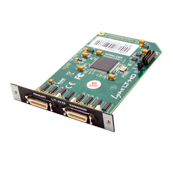
5.1 Locating the Serial Number of Your LT-HD To register your LT-HD, you must supply its serial number. The serial number is located on a label attached to the back (solder-side) of the LT-HD board, and also on the shipping carton. -
Page 7: Installation Procedure
Remove the AC power cord and take the top off of the Aurora 16 or Aurora 8. There are seven large screws plus one small screw near the center of the front faceplate. Before installing the LT-HD card, there is a jumper setting on the Aurora that corrects the current draw for an Aurora with an LT-HD. - Page 8 Remove the LSlot Expansion Port cover above the AES I/O Ports by removing the two mounting screws. Set these two screws aside, as they will be used to secure the LT-HD after installation. Remove the screw from the Aurora circuit board that is adjacent to the JP1 connector and the white serial number/barcode label.
- Page 9 Grounding yourself to the earth ground, remove the LT-HD from its protective static bag. Attach the multi-pin connector on the back edge of the LT-HD to the LSlot connector (JP1) on the Aurora mainboard. When the LT-HD connector pins appear to be lined up correctly with the Aurora LSlot connector press gently until the connector snaps into place.
- Page 10 Plug in and power up the Aurora using the front panel standby switch. You can see the LT-HD from the slits in the Aurora lid. If the green LED on the LT-HD lights up, the installation was successful. If the LED does not light, unplug the Aurora and re-mount the LT-HD, making sure that it is securely attached.
-
Page 11: External Connections
Since each DigiLink port is capable of 32-channels maximum, in 32-channel mode it would not be possible to connect a second interface to the LT-HD expansion port. The Channel Mode for the Aurora can be toggled from the front panel by pressing the TO ANALOG OUT button for ½... -
Page 12: Clock Settings
Primary and Expansion ports to connect all the units in series. Keep in mind that each Aurora used in this fashion needs to be equipped with an LT-HD card. It is also possible to connect LT-HD equipped Auroras in series with Digidesign or other third party HD-compatible interfaces. -
Page 13: Loop Sync
Currently the Aurora only supports Loop Sync completely when used as a clock master (true for LT-HD firmware revisions 1-5). We do intend to support Loop Sync slave operation in a future firmware update. Loop Sync is only applicable to cases where more than one interface is connected to the ProTools|HD system. -
Page 14: Protools Setup
9 ProTools Setup When an Aurora/LT-HD is connected to a Digidesign Core or Accel/Process card it will automatically be integrated as an I/O choice from within ProTools. Settings for attached interfaces are managed from the Hardware and I/O Setup pages within the ProTools Setup Menu. - Page 15 EXT (176.4/192) (176.4/192) or (176.4/192) or Wordclock or EXT + EXT + EXT + EXT/2* (176.4.2k/192k) EXT/2* (44.1/48) EXT/2* (44.1/48) (44.1/48)) * EXT/2 and EXT/4 clock rates are not supported in the early revisions of the LT-HD firmware. Page 12...
- Page 16 Aurora 16: 16- Aurora 8 Aurora 16: 32-channel mode channel mode 192 I/O #1 192 I/O #2 (channels 1-8) (channels 9-16) Sample All Supported All Supported All Supported Rates Causes LEDS on Causes LEDS on Causes LEDS on Aurora Front Aurora Front Aurora Front Identify...
- Page 17 = of project rate = of project rate = EXT/2 + EXT* EXT/2 + EXT* EXT/2 + EXT* * EXT/2 and EXT/4 clock rates are not supported in the early revisions of the LT-HD firmware. Page 14...
- Page 18 Aurora 16: 16- Aurora 8 Aurora 16: 32-channel mode channel mode 192 I/O #1 192 I/O #2 (channels 1-8) (channels 9-16) Analog In: Ref. Level A = +4 dBu (default) A = +4 dBu B = -10 dBV. Ch 1 A = +4 dBu A = +4 dBu (default) B = -10...
- Page 19 Aurora 16 : 16- Aurora 8 Aurora 16: 32-channel mode channel mode 192 I/O #1 192 I/O #2 (channels 1-8) (channels 9-16) Input Format 44.1 kHz- 96 kHz = N/A 44.1 kHz- 96kHz 44.1 kHz- 96kHz = 176.4 kHz – = N/A 192 kHz = 176.4kHz –...
-
Page 20: I/O Setup Page
9.2 I/O Setup Page This page within the ProTools software is where active input and output devices that are defined in the hardware setup page are assigned to record and play channels for use by tracks and busses within ProTools. Click on the INPUT, OUTPUT, and INSERT Tabs and click “default”... -
Page 21: Aurora Parameter Controls
10 Aurora Parameter Controls Since the Aurora with an LT-HD installed is intended to be accessed and identified as a Digidesign 192 I/O, all routing and system settings that are applicable for ProTools sessions should be initiated from within ProTools. There is no mechanism for parameter changes initiated from the interface device to be communicated and correctly displayed within the ProTools software. - Page 22 Aurora 8 Clock signal from the AES inputs 5-8. LSLOT Not applicable when used with the LT-HD. If no clock signal is available for the SYNC SOURCE selected, the LED for the selected source will flash, and the Aurora will operate from its internal clock.
-
Page 23: Aurora Remote Control Software
10.2 Aurora Remote Control Software The Aurora Remote Control software can operate on an OSX or Windows PC computer via a Lynx AES16 audio interface or MIDI. It can also operate on a Windows PC computer via IR. As is the case with the front panel controls, parameter selection is limited when the Aurora is operating in “ProTools LockOut”... - Page 24 Item Description Status Digital Input and Output Meters Functional Digital Output Monitor Source A and B monitor source selection Locked Out Digital Output Monitor Source A and B volume faders Locked Out Digital Output Monitor Source A and B mute controls Locked Out Digital Input Signal Status Functional...
-
Page 25: Updating The Firmware On The Lt-Hd
EEPROM is active. After programming the LT-HD for the first time, it is essential to remove the Aurora lid and check the status of jumper block JP2. If pins 1 and 2 are capped, than the LT-HD is operating off of the protected backup. In this case, place the jumper shunt over pins 2 and 3 for the new firmware to become active on the LT-HD. -
Page 26: Specifications
12 Specifications ORTS Number / Type One Primary, One Expansion Channels Aurora 8: 16 channels at all supported sample rates Aurora 16 - 16-channel mode: 16 channels at all supported sample rates Aurora 16 - 32-channel mode: 32 channels at all supported sample rates LOCK YNCHRONIZATION... -
Page 27: Support
13 Support We are devoted to making your experience with the LT-HD trouble-free and productive. If the troubleshooting and operational sections of this manual did not help resolve your questions, several support options are available to you: 13.1 Lynx Website Support Resources Logging on to http://www.lynxstudio.com/support.html will provide several options for resolving your... -
Page 28: Warranty Information
Lynx reserves the right to change or improve design of the product at any time without prior notice. Lynx Studio Technology, Aurora and the Aurora Logo are trademarks of Lynx Studio Technology, Inc. All other product or company names are the trademarks or registered trademarks of their respective owners.
Need help?
Do you have a question about the LT-HD and is the answer not in the manual?
Questions and answers