Advertisement
Quick Links
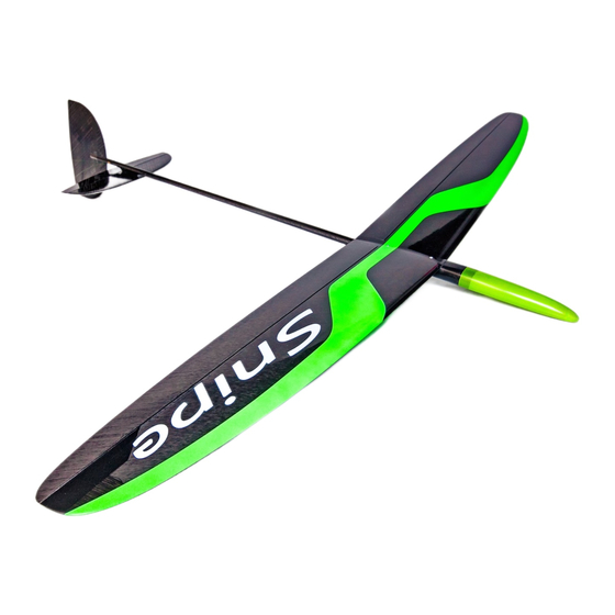
Snipe
Recommendations for assembly
Accessory kit:
1 - Horns wing (2 pcs);
2 – Launch T peg;
3 – Ballast nose mount;
4 - Stabilizer control horn (with slot)
5 – Vertical tail control horn (with hole);
6 - Torsion spring rudder and elevator;
7 - Screw for ballast M3;
8 - Screws stabilizer (2 pieces);
9 - Spare screws stabilizer (2 pieces);
10 - Set of screws for attaching the wing and M3 h10 M3x6
(1 set of spare);
11 - Cover wing controls;
12 - Pipes for sealing control cables;
13 – Flaperon control horn pivot axes.
1) ballast Snipe;
2) battery Shread-RC Smart Li-Po 650mAh or Shread-RC Smart Li-Po 450 mAh
3) Servos: JR 285 MG, FutabaS3155, MKS-DS6100, HyperionDS09-SCD, DymondD60; DymondD47 (Only the rudder);
4) receivers: Spectrum AR6255; Futaba 6008HS without the case; Futaba R6106HFC; Weatronic Clever 6 Receiver 2.4 Dual FHSS.
1)
superglue and liquid medium, the accelerator
2)
Cutter
3)
Masking tape
1. The list of parts and materials to build:
1 - Wing;
2 - Accessory Kit Snipe;
3 – Flaperon pushrod (2 pieces);
4 – Flaperon pushrod housing;
5 - Fuselage;
6 – Flaperon pushrod stiffener plate;
7 - Stabilizer;
8 – Vertical tail.
List of recommended hardware to run your model:
The list of materials needed to build the model:
Parts set:
4)
4) Pen and ruler
5)
5) Pliers
6)
6) Sandpaper number 240-320
1
Advertisement

Summary of Contents for Vladimir's Models Snipe
- Page 1 Parts set: 1 - Horns wing (2 pcs); 1 - Wing; 2 – Launch T peg; 2 - Accessory Kit Snipe; 3 – Ballast nose mount; 3 – Flaperon pushrod (2 pieces); 4 – Flaperon pushrod housing; 4 - Stabilizer control horn (with slot) 5 –...
-
Page 2: Assembling The Model
Snipe Recommendations for assembly 2. Assembling the model 2.1 Bonding of control horns in rudder and elevator. With a knife cut the slots in the elevator and rudder in these locations. (Fig. 2.1 - 2.2). Elevator horn isexactly in the center (along the axis of the stabilizer mounting holes) as the position must coincide with the slot in the pylon and tail boom. - Page 3 Snipe Recommendations for assembly Figure 2.6 - Sizing torsion feathers Figure 2.5 - Insert the torsion bar in the tail 2.3 Inset kylya in hvostovuyu beam Fix the rudder at zero deflection with masking tape. For the vertical tail, install it vertical relative to the stabilizer and wing (Figure 2.8), and center it with respect to...
- Page 4 Snipe Recommendations for assembly 2.4 Incorporation of tail surface control cables Insert the wire through the hole on the control horm. Using a tube for cables (which you'll find in the accessories kit) with a pair of pliers to crimp the cable as photo 2.10-2.11 To make a draft of the stabilizer of a cable loop and crimp its tube for fixing the rope.
- Page 5 Recommendations for assembly 2.5 Installing the aileron horns. Attention: Snipe wing pylon has a complex kinematics. Installing the horn the wrong location in the depth and the chord of the wing there can be interference with the upper wing skin . Figure 2.15 In order to provide clearance from the upper surface of the wing patch stick to the pylon .
- Page 6 Snipe Recommendations for assembly Fig. 2.18 – preparing axle bond with sandpaper Figure 2.20 - Bonding horns thick CA through the hole in the aileron Figure 2:19 – Gluing the flaperon axles Figure 2.22 - Bonding horn inside the aileron Figure 2.21 - Bonding horn inside the aileron...
- Page 7 Figure 2.26 - Placement of equipment in the nose Snipe Carefully wrap the servo case with strong thread ( Kevlar or other CBM ) (Figure 2.27).
- Page 8 Snipe Recommendations for assembly receiver at the front of the fuselage fairing (aft of the servos). attention: If you are using a servo thickness of 11 mm, pay attention to the location to ensure that there is no interference with the nose cone. (Figure 2.28 - 2.30).
- Page 9 Snipe Recommendations for assembly Figure 2:31 – Crimping of tube for tail control Figure 2.32 - ??? 2.8 Installing the aileron pushrods Figure 2.33 - Install the aileron linkage and the supporting carbon plates (green)
- Page 10 Snipe Recommendations for assembly Cut the flaperon tube housinge and carbon fiber plates in length, as shown in ( Figure 2.33 ) Glue the tube to the edge of the carbon plate with superglue . ( Figure 2.34) Insert the flaperon control rod/tube assembly into the fuselage .
- Page 11 Snipe Recommendations for assembly Figure 2.38 – Gluing flaperon stiffening carbon sheet Figure 2.39 - Fixing the aileron linkage inside the fairing 2.9 Insert a pin to roll into the wing...
- Page 12 Snipe Recommendations for assembly...
Need help?
Do you have a question about the Snipe and is the answer not in the manual?
Questions and answers