Table of Contents
Advertisement
Advertisement
Table of Contents

Summary of Contents for Vacon NX OPTC2
- Page 1 manual...
-
Page 2: Table Of Contents
Grounding jumper X1 ....................... 10 3.4 Bus terminal resistors........................ 11 3.5 Bus Biasing ..........................12 3.6 LED indications ........................... 13 INSTALLATION OF VACON NX RS-485 BOARD ..............14 COMMISSIONING ......................16 5.1 Fieldbus board parameters ......................16 MODBUS ........................... 19 6.1 Modbus RTU protocol, introduction .................... -
Page 3: General
Instead of sending and receiving information to and from frequency converters through I/O, you can connect them to a fieldbus. Vacon NX frequency converters can be connected to the RS-485 bus using a fieldbus board. The con- verter can then be controlled, monitored and programmed from the host system. -
Page 4: Rs-485 Option Board Technical Data
4 • vacon technical data RS-485 OPTION BOARD TECHNICAL DATA General Connections Interface OPTC2: Pluggable connector (5.08mm) OPTC8: 9-pin DSUB connector (female) Data transfer RS-485, half-duplex method Transfer cable Twisted pair (1 pair and shield) Electrical isolation 500 VDC Communications Modbus RTU As described in document “Modicon Modbus Protocol... -
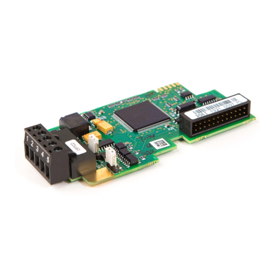
Page 5: Rs-485 Fieldbus Board Layout And Connections
• 5 RS-485 FIELDBUS BOARD LAYOUT AND CONNECTIONS Vacon RS-485 Fieldbus Board is connected to the fieldbus through either a 5-pin pluggable bus con- nector (board OPTC2) or a 9-pin female sub-D-connector (board OPTC8). The communication with the control board of the frequency converter takes place through the stan- dard Vacon Interface Board Connector. -
Page 6: Rs-485 Optc8 Option Board
6 • vacon layout and connections RS-485 OPTC8 option board Bus connector Jumpers Interface board connector Grounding plate Figure 2. Vacon RS-485 option board OPTC8 Signal Connector Description Shield Cable shield RxD/TxD-N Receive/ A DGND Data ground (reference potential for VP) Supply voltage –... -
Page 7: Grounding
Insert the data cables of both cables into terminals #3 (Line B) and #4 (Line A). Strip the cable at such a distance from the terminal that you can fix it to the frame with the grounding clamp. See 24-hour support +358 (0)40 8371 150 • Email: vacon@vacon.com... - Page 8 8 • vacon layout and connections Figure 5. Tel.+358 (0)201 2121 • Fax +358 (0)201 212 205...
-
Page 9: Grounding Only One Point On The Net
0.5 cm to fit in the terminals. See Figure 6. Note: Do this for both bus cables. 1 2 3 4 5 Shield Figure 6. Fix both the cables on the frame with the clamp. See Figure 7. Figure 7. 24-hour support +358 (0)40 8371 150 • Email: vacon@vacon.com... -
Page 10: Grounding Jumper X1
10 • vacon layout and connections Grounding jumper X1 3.3.3 The Grounding jumper X1 on the OPTC8 is used for grounding selection. If position ON is selected it means that the D-sub connector PIN1 is connected directly to ground. Selection of position OFF means that PIN1 is connected to ground via an RC-filter. -
Page 11: Bus Terminal Resistors
• 11 Bus terminal resistors If Vacon is the last device of the fieldbus line the bus termination must be set. Use jumper X4 (ON po- sition) or external termination resistors (e.g. in DSUB-9 connector). See Figure 9. Figure 9. Using jumper X4 to set the bus termination. -
Page 12: Bus Biasing
12 • vacon layout and connections Bus Biasing Bus biasing is required to ensure faultless communication between devices at RS-485 bus. Bus bias- ing makes sure that the bus state is at proper potential when no device is transmitting. Without bias- ing, faulty messages can be detected when the bus is in idle state. -
Page 13: Led Indications
Module is activated and receiving messages from the bus (once/sec) Blinking Module is in FAULT state slow • No messages from Master within the watchdog time (once/5 secs) • Bus broken, cable loose or Master off line 24-hour support +358 (0)40 8371 150 • Email: vacon@vacon.com... -
Page 14: Installation Of Vacon Nx Rs-485 Board
14 • vacon installation INSTALLATION OF VACON NX RS-485 BOARD Vacon NX frequency converter Remove the cable cover. Open the cover of the control unit. Tel.+358 (0)201 2121 • Fax +358 (0)201 212 205... - Page 15 Make sure that the grounding plate (see below) fits tightly in the clamp. Make a sufficiently wide opening for your cable by cutting the grid as wide as necessary. Close the cover of the control unit and the cable cover. 24-hour support +358 (0)40 8371 150 • Email: vacon@vacon.com...
-
Page 16: Commissioning
See Vacon NX User’s Manual, Chapter 7.3.3.1. Fieldbus board parameters The Vacon RS-485 board is commissioned with the control keypad by giving values to appropriate pa- rameters in menu M7 (for locating the expander board menu see Vacon NX User's Manual, Chapter... - Page 17 To see the present status of the RS-485 fieldbus, enter the page from (G7.5.2). See Figure 12 and Table 6 below. READY READY I/Oterm I/Oterm Monitor Comm. status 0.841 Good messages Error messages Figure 12. Communication status 24-hour support +358 (0)40 8371 150 • Email: vacon@vacon.com...
- Page 18 18 • vacon modbus Good messages 0…999 Number of messages received without communication errors Error messages 0…64 Number of messages received with CRC or parity errors Table 6. RS-485 message indications Tel.+358 (0)201 2121 • Fax +358 (0)201 212 205...
-
Page 19: Modbus
Examples are to read the ON / OFF states of a group of discrete coils or inputs; to read the data contents of a group of registers; to 24-hour support +358 (0)40 8371 150 • Email: vacon@vacon.com... - Page 20 20 • vacon modbus read the diagnostic status of the slave; to write to designated coils or registers; or to allow loading, recording, or verifying the program within the slave. When the slave responds to the master, it uses the function code field to indicate either a normal (er- ror-free) response or that some kind of error occurred (called an exception response).
-
Page 21: Supported Functions
CRC LO 47 hex 6.1.1.3 Preset Single Register The query message specifies the register reference to be preset. Registers are addressed starting with zero, i.e. register 1 is addressed as 0. 24-hour support +358 (0)40 8371 150 • Email: vacon@vacon.com... - Page 22 22 • vacon modbus Example of a request to preset register 42001 to 00001hex in Slave device 1: ADDRESS 01 hex Slave address 1 hex (= 1) FUNCTION 06 hex Function 04 hex (= 4) DATA Starting ddress HI 07 hex...
-
Page 23: Exception Responses
Invalid number of registers 0005 hex (= 5) No. of registers LO 05 hex ERROR CRC HI 34 hex CHECK CRC LO 66 hex CRC field 3466 hex (= 13414) Message frame: 24-hour support +358 (0)40 8371 150 • Email: vacon@vacon.com... - Page 24 24 • vacon modbus Exception response. Answer Slave – Master: ADDRESS 01 hex Slave address 1 hex (= 1) FUNCTION 14 hex Most significant bit set to 1 ERROR CODE 02 hex Error code 02 => Illegal Data Address ERROR...
-
Page 25: Modbus Interface
Modbus registers 6.2.1 The Vacon variables and fault codes as well as the parameters can be read and written from Modbus. The parameter addresses are determined in the application. Every parameter and actual value have been given an ID number in the application. The ID numbering of the parameter as well as the pa- rameter ranges and steps can be found in the application manual in question. -
Page 26: Process Data In
26 • vacon modbus Process Data Master -> Slave (max 22 bytes) Modbus register Name Range/Type 2001 32001, 42001 FB Control Word Binary coded 2002 32002, 42002 FB General Control Word Binary coded 2003 32003, 42003 FB Speed Reference 0…10000 %... -
Page 27: Process Data Out
6.2.3.1 Control word In Vacon applications, the three first bits of the control word are used to control the frequency con- verter. However, you can customise the content of the control word for your own applications because the control word is sent to the frequency converter as such. - Page 28 28 • vacon modbus 6.2.4.1 Status word UVFS TCSPDL Status word Status Information about the status of the device and messages is indicated in the . The word is composed of 16 bits that have the following meanings: Description Value = 0...
- Page 29 Process data out 1 to 8 Process Data Out values 1 to 8 can be used in application for various purposes. Update rate is 10ms for all values. See APPENDIX 1 for usage of these values. 24-hour support +358 (0)40 8371 150 • Email: vacon@vacon.com...
-
Page 30: Parameters
30 • vacon modbus Parameters 6.2.5 The parameter addresses are determined in the application. Every parameter has been given an ID number in the application. The ID numbering of the parameter as well as the parameter ranges and steps can be found in the application manual in question. The parameter value shall be given without decimals. -
Page 31: Example Messages
00 hex Number of registers 0003 hex (= 3) No. of registers LO 03 hex ERROR CRC HI F1 hex CRC F101 hex (= 61697) CHECK CRC LO 01 hex Reply frame: 24-hour support +358 (0)40 8371 150 • Email: vacon@vacon.com... - Page 32 32 • vacon modbus Example 2 Read the Process Data 42103…42104 with command (Read Input Registers). Command Master – Slave: ADDRESS 01 hex Slave address 1 hex (= 1) FUNCTION 04 hex Function 4 hex (= 4) DATA Starting ddress HI...
-
Page 33: Start-Up Test
• 33 Start-up test Frequency converter application Choose Fieldbus (Bus/Comm) as the active control place (see Vacon NX User's Manual, Chapter 7.3.3). Master software 1. Set FB Control Word (MBaddr 42001) value to 1hex. 2. Frequency converter status is RUN. -
Page 34: Metasys N2
34 • vacon metasys n2 METASYS N2 Metasys N2 Protocol Introduction The N2 communications protocol is used by Johnson Controls and others to connect terminal unit controllers to supervisory controllers. It is open to any manufacturer and based upon a simple ASCII protocol widely used in the process control industry. -
Page 35: Analogue Output (Ao)
All Internal Integer (ADI) points have the follwoing features: • Do not support Change of State (COS) reporting. • Can be overridden and the ”Override Active” bit will be set. However, the Internal value is un- changed (Read Only). 24-hour support +358 (0)40 8371 150 • Email: vacon@vacon.com... -
Page 36: N2 Point Map
36 • vacon metasys n2 N2 POINT MAP Analogue Inputs (AI) 7.3.1 Description Units Note Speed Setpoint 2 decimals Output Speed 2 decimals Motor Speed 0 decimal Load (power) 1 decimal Megawatt Hours Total Counter Motor Current 2 decimal Bus Voltage... -
Page 37: Binary Inputs (Bi)
2 decimals FBProcessDataIN 2 -32768 to +32767 2 decimals FBProcessDataIN 3 -32768 to +32767 2 decimals FBProcessDataIN 4 -32768 to +32767 2 decimals Table 21. These Analogue Outputs are application specific. 24-hour support +358 (0)40 8371 150 • Email: vacon@vacon.com... -
Page 38: Binary Outputs (Bo)
38 • vacon metasys n2 Binary Outputs (BO) 7.3.4 Description Comms Start/Stop Stop Start Comms Forward/Reverse Forward Reverse Reset Fault Reset FBFixedControlWord Bit_3 FBFixedControlWord Bit_4 FBFixedControlWord Bit_5 FBFixedControlWord Bit_6 FBFixedControlWord Bit_7 FBFixedControlWord Bit_8 FBFixedControlWord Bit_9 FBFixedControlWord Bit_10 FBFixedControlWord Bit_11 FBFixedControlWord Bit_12... -
Page 39: Fault Tracking
P2.7.22 fault 2=Fault,stop acc. to 2.4.7 3=Fault,stop by coasting 0=No response Response to slot 1=Warning P2.7.23 fault 2=Fault,stop acc. to 2.4.7 3=Fault,stop by coasting Table 25. Frequency converter responses to faults 24-hour support +358 (0)40 8371 150 • Email: vacon@vacon.com... - Page 40 40 • vacon metasys n2 APPENDIX 1 Process Data OUT (Slave to Master) The Fieldbus Master can read the frequency converter’s actual values using process data variables. Basic, Standard, Local/Remote Control, Multi-Step Speed Control, PID control and Pump and fan con-...
- Page 41 Reference for PID 0.01% controller 2005 Process Data IN2 Actual Value 1 to PID 0.01% controller 2006 Process Data IN3 Actual Value 2 to PID 0.01% controller 2007–2011 PD4–PD8 Not Used Table 29 24-hour support +358 (0)40 8371 150 • Email: vacon@vacon.com...
- Page 42 Find your nearest Vacon service centre Find your nearest Vacon office on the Extranet at: on the Internet at: www.extra.vacon.com www.vacon.com Manual authoring: documentation@vacon.com Document ID: Vacon Plc. Runsorintie 7 65380 Vaasa Finland Subject to change without prior notice © 2012 Vacon Plc.
Need help?
Do you have a question about the NX OPTC2 and is the answer not in the manual?
Questions and answers