
Summary of Contents for Matko XTP Series
- Page 1 Matko XTP Wireless Setup Manual Rev 1.1 XTP Radio Modules: Transmitter/Receiver Sets Bidirectional...
-
Page 3: Table Of Contents
Section 1 Wiring Diagrams Section 2 Speci cations Section 3 Con guration Section 4 Example Installations 9-12 Section 5 Troubleshooting/Before You Call 13-14 Section 6 Product Comparison/Compatibility Section 7 Part Numbers/Replacement Parts Section 8 Manual Revision RF Exposure WARNING: To satisfy FCC RF exposure requirements for mobile transmitting devices, a separation distance of 20 cm or more should be maintained between the antenna of this device and persons during device operation. -
Page 4: Wiring Diagrams
Section 1: Wiring Diagram For a typical scale applications, Connect one XTP Module as the transmitter (using BLACK Terminal Block) to the indicator and wire the second unit as the receiver (using the GREEN Terminal Block) to the Remote Display XTP as Transmitter (Indicator side) (Black Terminal Block) Indicator... -
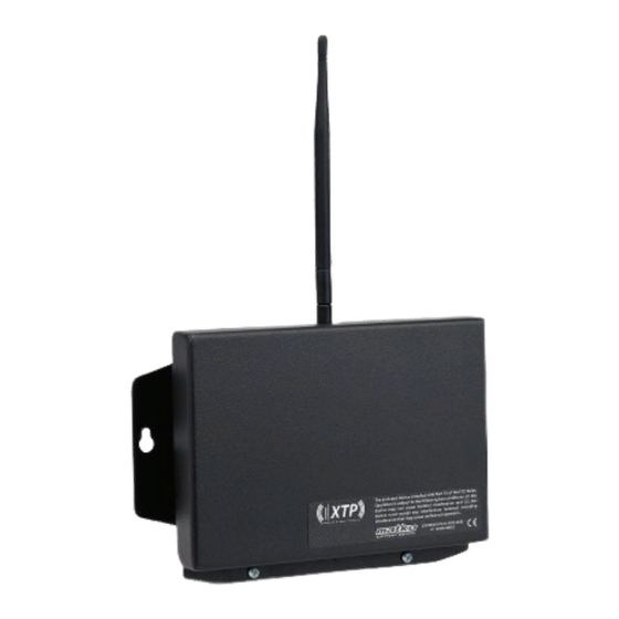
Page 5: Speci Cations
Power The XTP Module can run on any voltage source 7.5 VDC to 12 VDC with dedicated 250 mA. Power may be run o of Matko SBL and SSD Displays Range The XTP Module was designed under optimal conditions to run up to 2 miles outdoor Line of Sight. -
Page 6: Con Guration
Section 3: Con guration Con guration All units must be on the same ID to communicate with each other. There are 16 IDs available ( IDs 0 through 15) For each Radio in the system: Set the BLACK ID DIP switch to the desired ID BLUE BAUD RATE DIP Set the switch to match the serial device connected to the XTP unit. - Page 7 Section 3: Con guration Continued Optional IO (Input Output) Cards (Continued) Connect a switch between GROUND and the desired input line on the BLACK Input Card. When the switch is closed the GREEN Input LED will light. When the loop is open the light will be o . On the corresponding WHITE Output Card the Output LED will match the state of the GREEN...
- Page 8 Section 3: Con guration Continued ID +1 1200 IO 1-4 Board Layout ID +2 2400 Receiving ID +4 4800 Wireless 9600 ID +8 Signal 19200 Test Mode BAUD IO Card Slot 1 CONFIG RESET IO 5-8 Con g Step Con g IO Card Slot 2 XTP Transceiver R2 Figure 3.1: XTP Module (set to 1200 Baud ID1)
-
Page 9: Example Installations
Section 4: Example Installations Case 1 Typical Setup: Indicator to remote using two XTP Radio Modules. (Indicator wired for Current Loop and Display wired for RS422) TX CL+ TX CL - 422 LED Blink TX 422A TX 422B RX CL(-) Receiving Wireless Signal LED Blink RX CL(+) CLOOP LED Blink... - Page 10 Section 4: Example Installations Continued Case 3 Networked Indicators with Bi_Directional communication (RS422) TX 422A RX 422A TX 422B RX 422B RX 422A TX 422A RX 422B TX 422B 422 LED Blink Receiving Wireless Signal LED Blink TX 422A RX 422A TX 422B RX 422B RX 422A...
- Page 11 Section 4: Example Installations Continued Case 5 Indicator with a remote zero/print and button near the receiving XTP. (Indicator wired for RS422 and Display wired RS232) TX 422A RX 422A TX 422B RX 422B Ground GROUND Input Out 1 422 LED Blink (Installed Output Card) 232 LED Blink 232 TXD...
- Page 12 Section 4: Example Installations Continued Case 7 Indicator with a nearby switch to manually control a stoplight. The remote has a switch to remotely zero the indicator TX 422A RX 422A TX 422B RX 422B 422 LED Blink Ground GROUND (Installed Input Card in IO Card Slot 1) Input Out 5...
- Page 13 Section 5: Trouble Shooting BEFORE YOU CALL , please see if any of the below problems/solutions match your conditions. The Red PWR LED doesn’t come on Verify the power supply is turned on and putting out 7.5 to 12 volts DC and that the wires are securely screwed into the terminals.
- Page 14 Section 5: Trouble Shooting Continued Repeater If the system is working but you cannot get the needed range for the job site you can try to add an extra XTP to the system as a repeater unit. Mount the unit roughly in the middle of the distance with line of site to both ends. You will need power at this location.
-
Page 15: Product Comparison/Compatibility
Section 6: Product Comparison Product Comparison XT100 XT300 XT400 Legacy Legacy Legacy Line of Sight Distance Up to 1 mile Up to 1 mile Up to 1 mile Up to 2 Miles Baud Rate ▲ ▲ ▲ 1200 ▲ ▲ ▲... -
Page 16: Part Numbers/Replacement Parts
Section 7: Part Numbers Part Number Description Serial Data to Wireless Module XTP-R2 Serial Data to Wireless Module in expanded case. Includes 1 Output Card and 2 Relays XTP-R4 Serial Data to Wireless Module in expanded case. Includes 1 Output Card and 4 Relays XTP-R8 Serial Data to Wireless Module in expanded case.
Need help?
Do you have a question about the XTP Series and is the answer not in the manual?
Questions and answers