
Summary of Contents for Sega SuperBooth
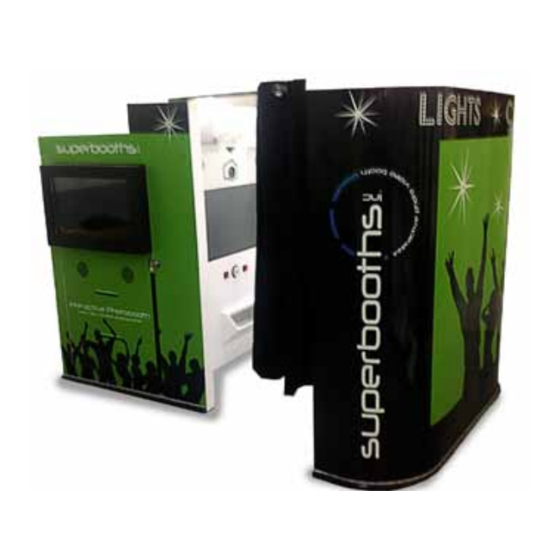
- Page 1 Version 6.19.12 SuperBooth Interactive Photo Booth Assembly and setup instructions. Serial # Distributed By Sales Person Technical Service #...
- Page 2 1. Prior to assembly, you must ensure there is sufficient space for placing or shifting this product. 2. Superbooth needs at least 3 people for assembly and to ensure your safety and the safety of others around you when moving this product.
-
Page 3: Unpacking Procedures
*Do not cut too deep or you’ll damage unit. 2. Open the cardboard box. 3. Remove back and middle wall from the pallet. 4. Remove the main SuperBooth pod from the pallet with a forklift or roll the pod off the pallet with a ramp. Insert power... - Page 4 Assembly Procedures 6. Align the middle wall [B] with the main pod [A]. Use the included hex key to lock the wall together. To lock [A] to [B] Insert the hex key and turn it counterclockwise [if you are on the inside of the booth] or clockwise [if you are on the outside of the booth] to engage both locks.
- Page 5 [Be careful to not hit the wires running through the rod]. 9. Connect the two LED connectors on the back wall of the Superbooth at points A/B and B/C and the two LED connectors at the end of the curtain rod.
- Page 6 Back Wall LED Strip Cover 1 LED Strip Cover 2 Side View Front View LED Strip Connector LED Strip Cover One Screw on the left and right side of the wire cover. Two Screws to mount LED cover SuperBooth Wall...
- Page 7 < > and line the 75" mar switch to switch to < > < > and line the 75" mark and line the 75" mark a very top of the view very top of the view very top of the view f and lock the c and lock the ca and lock the cam...
-
Page 8: Setting Up The Camera
Setting up the Camera Insert power supply into the bottom of the camera. Lift the small rubber cord tab and Run the cord out of the side. Attac Attac Attac Attac 2. Attach the lens. Atta Atta Align the white or Align Alig red index mark with... - Page 9 Setting up the Camera [continued] sert power sert power sert power sert power Under Under 5. Set the mode dial to <M> Under Under sert power Unde sert power Unde supply into supply into supply into supply into toolbar se toolbar se toolbar se toolbar se...
-
Page 10: Setting The Media
Setting the Media 1. Release the Open Lever and open the front cover. 2. Place the paper in the roll holders. Make sure the paper is not sticking out, and the edge of the rolls is snug against the paper. If the end of the roll us uneven (paper is sticking out), remove it from the holder and... - Page 11 Setting the Media [continued] 4. Remove a paper fixed tape, and insert the paper to the L line. 5. Fit the paper to the proper position for each size. L and 2L paper (6”) correspond to the L line. 6. The black form is inserted under the form guide. Insert the paper in the direction of the arrow until you hear a beep (close to the line shown below).
- Page 12 select Quality Plug (Default is L) into the left side o Change this setting < > Setting the Media [continued] 7. Set the ribbon into the printer. Unite and insert as shown below. Turn the take-up side of the ribbon in the direction indicated by the arrow to take up any slack.
- Page 13 et the mode Mount Have a subject stand against Have a subject stand agains Have a subject stand against Have a subject stand agains Align the lens’ Have a subject stand agains dial to dial to dial to dial to Have a subject stand agains <...
- Page 14 " mark at the cable cable cable mera mera he view finder mera mera amera amera k the camera. nd against the he Superbooth in all the way. the camera on and zoom out all of the way.
- Page 15 40" Television Product #: BG-192001 32" Television Product #: BG-192002 Subwoofer Product #: BG-192007 Air Mover Product #: BG-192008 12V Power Supply Product #: BG-192010 LED Photo Light [x2] Product #: BG- 192005 Amplifier [x2] Product #: BG-192004 6.5" Speakers [Pair x2] Product #: BG-192003 Printer [x2] Product #: BG-192006...
- Page 16 Connecting the Keyboard & Mouse 1. Please shut off the Superbooth PC. You will need to remove the credit board USB cable from the front of the PC. [It is in the opposite USB port of the small Superbooth USB key].
- Page 17 1. Locate the two bolts on the back of part [A]. They are on either side of the forklift hole. Bolt 1 Bolt 2 2. Use the socket wrench to remove the two bolts from the metal Superbooth frame. Pull out the frame from here.
- Page 18 Black wire from Red wire from switch to ground. switch to port 4. 7. Turn on the machine and after the Superbooth program starts flip the switch to on to get to the blue settings screen.
- Page 19 Note before assembling 1. Prior to assembly, you must check to see if you have pre-drilled holes on the top of the Superbooth. If you do not have pre-drilled holes please refer to the Superbooth Topper Mounting Hole template.
- Page 20 Topper Mounting Instructions [continued] 1. Remove plastic protective sheets on the 32” monitor. 2. Slide the 32” monitor into the topper. 3. Insert the shorter bolts through each of the 4 mounting holes in the topper and thread them into the back of the monitor.
- Page 21 Super Booth. 5. Line up the topper base with the 4 holes on the top surface of the Superbooth. 6. Place two washers on each of the longer bolts and thread them into each of the four mounting holes.
- Page 22 Topper Mounting Instructions [continued] 7. Insert the HDMI cord into HDMI slot 1. HDMI Port 1 8. Chase the HDMI cable and the monitor power cord through the chase hole on back of the topper mount. Wire Chase Hole for Power and HDMI cable.
- Page 23 Connection of DVI to HDMI adapter, HDMI splitter, and HDMI Cables to the PC. HDMI Port location on both Topper and Door Monitor HDMI Port 1...
- Page 24 Topper Mounting Instructions [continued] 9. Turn off the Superbooth PC with the power button on the front. 10. Locate the back of the PC. Remove the DVI to HDMI cable located in DVI port 2 [A] on the back of the PC.
- Page 25 Note before assembling 1.You will need to turn off the Superbooth and pull out the metal framed unit from part [A] in order to access the inside of the unit.
- Page 26 Counter Installation Manual [continued] 1. Connect the 5V Counter to the Wire Lead. Connect the red and black wire of the 5V Counter to the like colors on the wire lead. DBA Pulse Lead 5V Power Lead 5V Counter 2. Use the screws included to mount the 5V Counter to the side wall of the 40”...
- Page 27 Counter Installation Manual [continued] 3. Remove the screws that hold the credit board to the inside wall of the Superbooth. Be careful to not disconnect any wires. You just need to be able to access the board to solder a wire to it.
- Page 28 Counter Installation Manual [continued] 6. Once the wires are untwisted you will need to cut the yellow wire in the top left hole [harness clip facing up]. Cut the yellow wire about 3” from the harness. 7. Now take the black wire lead from the Counter and twist the two cut yellow wires and black lead wire together.
- Page 29 SuperBooth DBA Lock box Setup Manual Lock box Installation Manual For your own safety, please read through this instruction manual that we have prepared for you thoroughly and take precautions when using the product. Note before assembling 1. You may need to pull the frame out of the main unit [A] to install the Lock box over the DBA.
- Page 30 Lock box Setup Manual [continued] 1. Place the lock box over the DBA so it rests on top of the DBA and the front is flush with the back of the face. 2 Place the adjustable staple on the hasp and fully extend the hasp and staple so it touches the white wall of the TV mount.
- Page 31 Lock box Setup Manual [continued] 5. Slide the lock box over the DBA and slide the hasp over the staple to make sure it aligns properly. Lock box hasp. Lock box staple. 6. To mount your lock box to secure the DBA slide the metal box over the DBA and slide the hasp over the staple.
- Page 32 DBA Lock Box Removal Manual 1. To remove the Lock Box to access the DBA you will need to remove your lock first. 2. Fold the hasp down off of the lock staple. Lock Box staple. Lock Box hasp.
- Page 33 3. To remove the Lock Box slide the DBA to the left while rotating it counterclockwise and sit it on the bottom floor of the SuperBooth frame. 4. To replace the Lock Box lift it up and set it on the DBA.
- Page 34 SuperBooth LED Strip Diagram LED Strip Light [2] - BG-192023 LED Strip Light [3] - BG-192024 LED Strip Light [1] - BG-192022 LED Strip Light [4] - BG-192025...
- Page 36 SuperBooth Parts List [continued] Product # Description BG-192041 DVI to HDMI Cable BG-192042 USB Printer Cable BG-192043 USB Credit Board Cable BG-192044 White Box USB Cable BG-192045 RCA to 1/8" Cable BG-192046 Audio 1/8" Splitter BG-192047 DC Power Cables BG-192048...
- Page 37 SuperBooth Parts List Product # Description ainst the nst the BG-192001 40" Monitor st the perbooth BG-192002 32" Monitor erbooth BG-192003 6.5" Speakers rbooth the way.
- Page 38 For Spares and Technical Service please contact Play It! Amusements, Inc. Play It! Amusements, Inc. Play It! Amusements, Inc. 252 Beinoris Drive Wood Dale, Illinois 60191 1 (847) 364-9787 sales@segaarcade.com...
Need help?
Do you have a question about the SuperBooth and is the answer not in the manual?
Questions and answers