Table of Contents

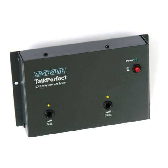
Summary of Contents for Ampetronic TalkPerfect DX
- Page 1 TalkPerfect™ DX Installation Guide Copyright ©2011-19 Ampetronic Ltd TalkPerfect ™ Speech Transfer System for Glazed Security Screens Installation Guide P a g e Doc No: UP27006-5 - Ampetronic Ltd. +44 (0)1636 610062 www.ampetronic.com...
-
Page 2: Table Of Contents
User Serviceable Parts ........................18 Commissioning ............................18 Handover ............................18 User Training ............................. 18 Warranty Statement ..........................19 Appendix 1 ............................20 Appendix 2 ............................20 P a g e Doc No: UP27006-5 - Ampetronic Ltd. +44 (0)1636 610062 www.ampetronic.com... -
Page 3: Copyright Notice
All rights reserved, any unauthorised, copying or reproduction will constitute an infringement of Copyright, Ampetronic asserts its rights as the owner and producer of this document. This document is not be sold, hired or otherwise commercialised without the written consent of Ampetronic. -
Page 4: Pre-Requisites Checklist
(to avoid injury) taking into account final furniture and other equipment locations. The TalkPerfect™ DX system uses “Solder-less” connections thereby negating the need for “Hot Works” permits or other Health and Safety issues concerned with Soldering. P a g e Doc No: UP27006-5 - Ampetronic Ltd. +44 (0)1636 610062 www.ampetronic.com... -
Page 5: Other Equipment
600mm should be adhered to at all times. Spacing less than this should be agreed with Ampetronic or the distributor before installation can commence, as this will reduce the overall efficiency achievable by the system. -
Page 6: Cable Routing & Fixing
On each microphone and speaker 2.5 metres of cable are provided to allow for optimal cable routing and fixing. Ampetronic does not recommend that cables are cut-to-length as this can introduce connection issues; all peripherals are terminated with cable ferrules to facilitate effective solder-less connections. -
Page 7: Acoustic Conditions
Sound pressure level checks may be performed prior to installation or at the point of site survey. Rectification of such excessive ambient noise can be costly. Figure 3 - Acoustic Feedback Paths P a g e Doc No: UP27006-5 - Ampetronic Ltd. +44 (0)1636 610062 www.ampetronic.com... - Page 8 The recommendation of a distance of 200mm or less will give the best performance. Correct use of the Combi unit In-correct use of the Combi unit P a g e Doc No: UP27006-5 - Ampetronic Ltd. +44 (0)1636 610062 www.ampetronic.com...
-
Page 9: Installation
The L.E.D. Combi has additional cabling to drive the L.E.D Function, using both ‘Staff’ and ‘Control’ connectors: Staff connector Connection Legend Colour Usage Blue Bias voltage Microphone Staff Microphone Yellow Ground Staff Microphone P a g e Doc No: UP27006-5 - Ampetronic Ltd. +44 (0)1636 610062 www.ampetronic.com... - Page 10 Dimensions for Combi Speaker/Microphone (Outside Dimensions) Width = 96mm Depth = 140mm Height = 85mm Gooseneck Microphone Height = 400mm Figure 5 - Combi Base Size P a g e Doc No: UP27006-5 - Ampetronic Ltd. +44 (0)1636 610062 www.ampetronic.com...
-
Page 11: Pod Installation
Planning and execution are critical to gaining optimum performance from the system. P a g e Doc No: UP27006-5 - Ampetronic Ltd. +44 (0)1636 610062 www.ampetronic.com... - Page 12 Figure 7 - Glass Mount Microphone - Mounting Figure 6 – Glass Mount Microphone Microphone element face Noise Reduction Port Mounting face P a g e Doc No: UP27006-5 - Ampetronic Ltd. +44 (0)1636 610062 www.ampetronic.com...
- Page 13 TalkPerfect™ DX Installation Guide Copyright ©2011-19 Ampetronic Ltd P a g e Doc No: UP27006-5 - Ampetronic Ltd. +44 (0)1636 610062 www.ampetronic.com...
-
Page 14: Talkperfect™ Amplifier Connections
(g) on the TalkPerfect™ to the line input of the CLD1. Set the select switch on the CLD1 to the ‘LINE’ position. Figure 9 - CLD1 Connection Diagram P a g e Doc No: UP27006-5 - Ampetronic Ltd. +44 (0)1636 610062 www.ampetronic.com... -
Page 15: Set-Up
‘window’ where this is neither too loud or too quiet, i.e. the recommended setting. P a g e Doc No: UP27006-5 - Ampetronic Ltd. +44 (0)1636 610062 www.ampetronic.com... -
Page 16: Setting System With Assistance
Faults that may occur during a systems lifetime will typically be due to mechanical operations that occur in system usage. These typically would be mechanical on/off switches on items of equipment. P a g e Doc No: UP27006-5 - Ampetronic Ltd. +44 (0)1636 610062 www.ampetronic.com... - Page 17 ‘Staff’ side volume adjustment full up, approx. 8Ω, with the 4-way connector ‘Rub’ the face of the ‘Client’ microphone DISCONNECTED from the TalkPerfect™ DX amplifier on the speaker connections P a g e Doc No: UP27006-5 - Ampetronic Ltd. +44 (0)1636 610062 www.ampetronic.com...
-
Page 18: User Serviceable Parts
User training will consist of equipment and system component familiarisation, microphone techniques, and “best practice” when using the system. P a g e Doc No: UP27006-5 - Ampetronic Ltd. +44 (0)1636 610062 www.ampetronic.com... -
Page 19: Warranty Statement
The warranty does not cover any such modification or adaption and Ampetronic will not be held responsible for any costs resulting from such a modification or adaption. - Page 20 Appendix 1 Speaker/Microphone Pod Dimension Data Appendix 2 Glass Mount Microphone Dimensional Data P a g e Doc No: UP27006-5 - Ampetronic Ltd. +44 (0)1636 610062 www.ampetronic.com...


Need help?
Do you have a question about the TalkPerfect DX and is the answer not in the manual?
Questions and answers