Advertisement
ZX832-3 Addressable Optical/Heat
Multisensor Installation Sheet
1
3
EN: Installation Sheet
Description
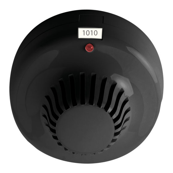
The ZX832-3 Addressable Optical/Heat Multisensor integrates
both high sensitivity smoke and thermal sensors, resulting in
higher detection certainty. See Table 1 for a list of models. For
a complete list of sensing profiles refer to Table 2.
Table 1: Models
Number
Description
ZX832-3P
Addressable Optical/Heat Multisensor, Polar White
ZX832-3B
Addressable Optical/Heat Multisensor, Black
ZX832-3S30
Addressable Optical/Heat Multisensor, Chubb
© 2015 UTC Fire & Security. All rights reserved.
2
4
Figures
Figure 1: Inserting a detector
Figure 2: Position of the locking tab
Figure 3: Removing a locked detector
Figure 4: Setting the address
Installation
Note:
For general guidelines on system planning, design,
installation, commissioning, use and maintenance, refer to the
EN 54-14 standard and local regulations.
To install a detector:
Insert the detector head into the mounting base and rotate it
clockwise until it clicks into place (Figure 1).
The detector may be locked into the mounting base if required.
To do this, remove the locking tab before installation shown in
Figure 2.
1 / 4
P/N 10-4211-501-ZX01-01 • ISS 26JAN15
Advertisement
Table of Contents

Related Manuals for Ziton ZX832-3 Series

Summary of Contents for Ziton ZX832-3 Series
- Page 1 ZX832-3 Addressable Optical/Heat Multisensor Installation Sheet Figures EN: Installation Sheet Figure 1: Inserting a detector Figure 2: Position of the locking tab Description Figure 3: Removing a locked detector The ZX832-3 Addressable Optical/Heat Multisensor integrates both high sensitivity smoke and thermal sensors, resulting in Figure 4: Setting the address higher detection certainty.
- Page 2 After installation, ensure that the detector communicates with Specifications the control panel. Always test detectors after installation. Operating voltage 19.5 to 20.5 V pulsed, To remove a locked detector: max. 4 V line loss Current Insert a small screwdriver into the locking tab slot Standby 600 µA (Figure 3).
- Page 3 Contact information For contact information, see www. utcfssecurityproducts.eu. Table 2: Sensing profiles Profile Sensitivity Notes Smoke only - High Smoke only response, Sensitivity 1 Very high sensitivity Smoke only - Normal Smoke only response, Sensitivity 2 (std) Normal sensitivity 3 [1] Smoke only - Medium Smoke only response, Sensitivity 3 Medium sensitivity [1]...
- Page 4 4 / 4 P/N 10-4211-501-ZX01-01 • ISS 26JAN15...
Need help?
Do you have a question about the ZX832-3 Series and is the answer not in the manual?
Questions and answers