
Related Manuals for Müthing MU-B

Summary of Contents for Müthing MU-B
- Page 1 OPERATION MANUAL EN | Original MU-B EX MACHINE No 2015 EDITION 02.2020 REFERENCE NUMBER MU-B-AGRIA_BA_15_2020-02_EN...
- Page 2 Machine identification In order for your dealer to assist you as efficiently as possible, you will need to provide some information about your machine. Please enter the information here. Designation Working width Weight Machine number Additional equipment Dealer's address Manufacturer's address Müthing GmbH &...
-
Page 3: Handover Declaration
Handover declaration Handover declaration – Fill out this sheet with your dealer. – Then separate this sheet from the operating manual and send it to the manufacturer within 10 days of delivery. Only in this way will the guarantee be effective from the date of delivery Müthing GmbH &... - Page 4 Handover declaration...
-
Page 5: Handover Declaration - Copy
Handover declaration – Copy Handover declaration – Copy – This sheet remains with the client in the operating manual I have bought the machine described below from Müthing GmbH & Co KG, Soest, and confirm full delivery and handover of the machine including the operating manual and spare parts list, as well as training in operating the devices with safety instructions and warning information from your dealer. - Page 6 Handover declaration – Copy...
-
Page 7: Table Of Contents
Index ............Designation of components For your notes ........... Technical specifications Delivery and assembly ......25 Checking the scope of delivery MU-B adapter ..........26 Coupling the machine ....... 27 With support wheels Without support wheels Coupling Tyre diameter Preparation ..........30 Working depth Driving on the road ........ -
Page 8: About This Operating Manual
About this operating manual Target group This operating manual is intended for trained machine operators and About this operating manual persons who are otherwise qualified to carry out landscape work and who have received training in how to use this machine. Safety Familiarise yourself with the contents of this operating manual which are relevant for your activity before commissioning or assembling the... -
Page 9: Symbols
About this operating manual Symbols In order to make this manual clear and easy to read, we have used var- ious symbols. They are explained below: • A bullet point accompanies each item in a list A triangle indicates operating functions which must be performed ... -
Page 10: Safety
Safety For your safety This chapter contains general safety instructions. Each chapter of the Safety operating manual contains additional warning instructions which are not described here. Observe the safety instructions: • in the interest of your own safety, • in the interest of the safety of others •... - Page 11 Safety Meaning of warning Read the operating manual carefully and follow the instructions Commissioning of the machine must not take place before the operating signs manual has been read and understood. This particularly applies to safe- ty instructions. Do not stand between the carrier vehicle and the machine Standing between the carrier vehicle and the machine while the engine is running is prohibited, especially during coupling and uncoupling.
-
Page 12: Definitions
Safety Definitions All direction information is given in relation to the direction of travel of the machine: Front Right Rear Left Down Who is allowed to Only qualified personnel Only qualified persons who have been informed of the dangers associ- operate the ated with handling the machine are permitted to operate, service or re- machine? -
Page 13: Coupling
Safety Coupling Increased risk of injury When the machine is being coupled to the tractor, there is an increased risk of injury. Therefore: • Only couple the machine with the road chassis raised • Secure the tractor against rolling away •... -
Page 14: Centre Of Gravity
Safety Centre of gravity Observe the total weight, axle loads, tyre load-bearing capacity and minimum ballast specifications The front or rear mounting of machines must not cause the tractor's per- missible total weight, its permissible axle load or its tyre load-bearing capacity to be exceeded. - Page 15 Safety Calculation The measured values can now be inserted into the formulae. Ballast with front weights Calculating the ballast with front weights on rear-mounted machines. – H Front ballast in kg = ------------------------------------------------------------------------------------------ - Ballast with rear weights Calculating the ballast with rear weights ...
-
Page 16: Road Transport
Safety Road transport Make sure that the condition of the machine conforms to road traf- fic regulations The machine must conform to current traffic regulations if you intend to drive it on public roads. This includes for example: • Fitting lighting equipment, warning devices and protective devices •... - Page 17 Safety Do not remove the protective equipment The protective equipment must not be removed or by-passed. Check all protective equipment before starting the machine. Unprotected ma- chine parts can cause serious or fatal injury. Riding on the machine is strictly prohibited People or objects must never be transported on the machine.
-
Page 18: Uncoupling The Machine
Safety Uncoupling the Increased risk of injury There is an increased risk of injury when uncoupling the machine from machine the tractor. Therefore: • Secure the tractor against rolling away • Never stand between the tractor and the machine during uncoupling •... -
Page 19: Further Regulations
Safety Replace hydraulic hoses Replace hydraulic hoses every six years. Hydraulic hoses can age with- out any externally visible damage. Defect hydraulic lines can lead to se- vere or fatal injuries. Caution when cleaning with a high-pressure cleaner The machine can be cleaned using either water or a steam jet. Only use a low pressure to clean bearings, fans, signal mixer units, plastic parts and hydraulic hoses. -
Page 20: Familiarising Yourself With The Machine
Familiarising yourself with the machine This chapter contains general information on your machine as well as Familiarising yourself with the machine information on: • Range of application • Features • Designation of components • Technical specifications Range of applica- The machine is only allowed to be used for its intended purpose in land- scaping or similar fields of work in accordance with its tooling. -
Page 21: Features Of The Machine
Familiarising yourself with the machine Features of the Robust housing in optimised form The housing is particularly robust for heavy use and is designed in an machine optimised form. Power transmission In the case of mechanically driven machines, power is transmitted to a gear box using a PTO shaft. -
Page 22: Designation Of Components
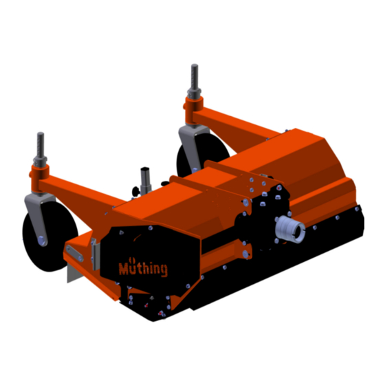
Familiarising yourself with the machine Designation of components Mechanical drive Gear box Housing Connection to car- rier vehicle [+] Front stone impact protection Support leg Front support wheels [+] Runner Deflector Deflector Protective cover for V-belt Rear stone impact protection Wear insert [+] Roller Rotor... -
Page 23: Technical Specifications
Familiarising yourself with the machine Technical specifi- cations Height Width Depth Mechanical drive Mechanical drive MU-B AGRIA 80 MU-B AGRIA 100 MU-B AGRIA 120 Height (m) Without support wheels 0,38 0,38 0,38 With support wheels 0,55 0,55 0,55 Width (m) -
Page 24: Mu-B Agria 80
Familiarising yourself with the machine Mechanical drive MU-B AGRIA 80 MU-B AGRIA 100 MU-B AGRIA 120 Category Flange sleeve Centring pivot Centring pivot Centring pivot adapter adapter adapter Paint colours Yellow RAL 2002 RAL 2002 RAL 2002 Black RAL 9005... -
Page 25: Delivery And Assembly
Delivery and assembly Checking the The machine is delivered completely assembled. If parts of the machine Delivery and assembly have not been assembled, please contact your dealer. scope of delivery Do not assemble the machine yourself Do not perform assembly work yourself since requirements for an orderly condition of the machine are : •... -
Page 26: Mu-B Adapter
MU-B AGRIA adapter The machine must be fitted with a suitable adaptor in order to be at- MU-B AGRIA adapter tached to a carrier vehicle. Before attaching the machine, you should therefore check whether the correct adaptor for your carrier vehicle is present on the machine. -
Page 27: Coupling The Machine
Coupling the machine Coupling the machine Increased risk of injury There is an increased risk of injury when the machine is being cou- pled to the carrier vehicle. Therefore: • Secure the carrier vehicle so that it cannot roll away. •... -
Page 28: Coupling
Coupling the machine Coupling Carefully drive the carrier vehicle towards the machine. Connect the flange sleeve on the carrier vehicle to the adapter on the machine. Ensure that it is securely engaged. Adapter Flange sleeve Secure the carrier vehicle so that it cannot roll away. ... -
Page 29: Tyre Diameter
Coupling the machine Tyre diameter The machine must be set in accordance with the tyre diameter of the carrier vehicle so that, when in the work position, the runners are paral- lel to the ground. Lower the machine to its work position ... -
Page 30: Preparation
Preparation Working depth Without support wheels, the working depth can be adjusted in 10 mm Preparation steps. With support wheels, the working depth can be adjusted in 15 mm steps. The optimal working depth for most applications is the middle setting. Tools must not come into contact with the ground Any contact with the ground could result in stones or other material not being held back safely by the stone impact protection. -
Page 31: Driving On The Road
Driving on the road Transport position Driving on the road Use the carrier vehicle to set the height so that the machine is high enough for transport Secure the control devices on the carrier vehicle so that they cannot ... -
Page 32: Mulching
Mulching Task Mulching Check the hazard area The hazard area in front of the machine is 8 m. It is 2 m at the sides. Before driving off, operating the machine and during operation, Hazard area check its hazard area. Make sure that you have an adequate view. Do not begin work until the hazard area is cleared of any persons or objects. - Page 33 Mulching Particular care should be taken by the operator when working with the mulcher. Working on ditches, overhangs or slopes are activities which tend to be particularly hazardous. We can only give general instruc- tions, the actual situation must be evaluated by the operator.
- Page 34 Mulching Do not lean the machine forwards The machine must not lean forwards or backwards during work. A machine that is leaning forwards or backwards can become clogged up and work incorrectly. Lower the machine using the carrier vehicle until the machine is on ...
-
Page 35: Cleaning And Care
Cleaning and care Cleaning A high-pressure cleaner, for example, can be used to clean the ma- Cleaning and care chine. Never point the water jet directly at the labels or type plate. Only use low pressure to clean the bearings Only use low pressure to clean the bearings. -
Page 36: Parking And Storage
Parking and storage Setting down the Parking and storage machine in a Ensure that there are no unauthorised persons can enter the set-down location secure position If the machine is set down either coupled to the carrier vehicle or uncoupled, you must make sure that it is protected so that unau- thorised persons have no access to it. -
Page 37: Without Support Wheels, In
Parking and storage Without support wheels Move the support leg out of the parking position Support leg Parking Retainer position Attach the support leg to the front of the machine and secure Retainer Lowering the machine Disconnect the machine from the carrier vehicle ... -
Page 38: Maintenance
Maintenance For your safety Maintenance Special safety instructions Requirements for conducting maintenance work Only perform the maintenance work if you have the required expert knowledge and suitable tools. A lack of specialist knowledge or the use of unsuitable tools can cause accidents. -
Page 39: General Information
Maintenance Protective measures Additives in oils and lubricants may have adverse effects on health. Since the hazardous material code does not require any special identi- when handling oils or fication, please always observe the following: lubricants Avoid skin contact Avoid skin contact with these materials. Contact can result in skin damage. - Page 40 Maintenance Fundamentals The following table contains a brief explanation of the most important terms used for maintenance. Task Version • Greasing Apply grease to the slide surfaces us- ing a brush • Lubrication Unless specified otherwise, one or two strokes with the grease gun pro- vide sufficient lubrication •...
- Page 41 Maintenance Screwed connections Retighten screws All bolts must be retightened: • After the first hours of operation • According to the frequency of use • But at least once a season General tightening torques Tighten all screwed connections in accordance with the information in the table.
-
Page 42: Maintenance Intervals And Setting Work
Maintenance Maintenance inter- The information relates to average usage under the machine's normal operating conditions. Maintenance intervals are shorter for heavy us- vals and setting age, such as with hire companies, or for extreme operating conditions work such as very dusty environments. General •... -
Page 43: Lubricating Work
Maintenance Lubricating work Lubricate bearings The bearings must be lubricated regularly. Lubricate only with one or two strokes from the grease gun: • According to the maintenance chart • After heavy use • But at least once a season Bearings that require no maintenance must not be lubricated. - Page 44 Maintenance Overview of lubri- cation points S = lubrication point Other lubrication The following applies: • points In addition to the lubrication points shown in this operating manual, your machine may have other lubrication points • As a rule, lubrication points are located at pivots or bearings. There- fore, inspect your entire machine for any such additional lubrication points.
-
Page 45: Gearbox Oil
Maintenance Gearbox oil The gearbox oil must conform to the specification. Chapter »Familiarising yourself with the machine«, section »Techni- cal specifications«, page 23 Check Twice per season Loosen the screw on the inspection opening with an Allan key and ... - Page 46 Maintenance Replacement 1x per season Place a collection container under the outlet for the waste oil Outlet Loosen the screw on the inspection opening using a hex key Inspection opening Loosen the screw on the outlet with an Allan key and remove the ...
-
Page 47: Tools
Maintenance Tools The tools must be replaced if they: • Are damaged As required • Are heavily worn • The bore on the tool is worn • The fastening screws or the fastening nuts are worn It is important that the rotor runs without unbalance. Therefore: •... -
Page 48: V-Belt
Maintenance V-belt The V-belt is tensioned by a counterweight. If the V-belt is not sufficient- ly tensioned, it must be retensioned. If there are any tears or the V-belt is damaged, it must be replaced. As required Checking There is an inspection opening on the machine. Check the tension of the V-belt. - Page 49 Maintenance Replacement If there are any tears or other damage on the V-belt, it must be replaced. Remove the screws, remove the safety cover. Screws Screws Safety cover Remove the spring from the holder Bracket Use the bolt to slacken the V-belt tension ...
-
Page 50: Runners
Maintenance Runners The runners protect the machine from direct contact with the ground. If they are not replaced in good time, the housing of the machine will be damaged. As required Secure the machine Work can only be carried out on a machine secured against rolling away and dropping. -
Page 51: Additional Equipment
Additional equipment Wear insert A metal insert protects the housing from wear. Additional equipment Y blade set Y blades require less power during work. When using a Y blade set, the rotor must be replaced at a specialist workshop. It is not possible to as- semble the Y blades on a standard rotor. -
Page 52: Support Wheels
Additional equipment Support wheels Support wheels are available for comfortable depth guidance. Operating hours An electronic operating hours counter displays the actual operating du- ration. This means that data can be recorded precisely and used, for ex- counter ample, for calculations. -
Page 53: Fault Elimination
Fault elimination Faults can often be eliminated quickly and easily. In the event of hydrau- Fault elimination lic problems, first check: • Are the hydraulic hoses properly connected? • Is the control valve on the carrier vehicle defective? If so, contact your dealer. •... - Page 54 Fault elimination Fault Cause Remedy Gear box overheating Incorrect oil specification Change oil and select oil with cor- rect specification Oil too old Change oil Oil level too low Fill the oil to the lower edge of the inspection opening Machine overload Maintain rpm in correct region, ad- just driving speed to suit the work,...
-
Page 55: Disposal Of The Machine
Disposal of the machine When the service life of your machine is over, it must be disposed of Disposal of the machine properly. Please observe currently valid disposal regulations. Metal parts All metal machine components can be sent for metal recycling. Plastic parts All plastic parts are marked and can be recycled. -
Page 56: Ec Declaration Of Conformity
EC Directive 2006/42/EC: Type plate and CE symbol MU-B AGRIA and accessories Soest, 27.12.2017 Christian Jungmann CEO and authorised person for compiling technical documentation Copy of the type plate/serial number entry... - Page 57 Index Index Additional equipment Range of application Counter cutter Carbide M shackle flails Operating hours counter Support wheels Wear insert Assemblies Safety Agricultural training axle loads Care and maintenance work Care Centre of gravity Centre of gravity Check the screwed connections Cleaning Cleaning Coupling...
- Page 58 For your notes For your notes...
- Page 59 For your notes...
- Page 60 Müthing GmbH & Co. KG Soest Am Silberg 23 59494 Soest +49 (0) 2921 96510 +49 (0) 2921 73080 soest@muething.com Müthing GmbH & Co. KG Uffenheim Am Brünnlein 2 97215 Uffenheim +49 (0) 9842 98660 Fax +49 (0) 9842 986667 WWW.MUETHING.COM uffenheim@muething.com...
Need help?
Do you have a question about the MU-B and is the answer not in the manual?
Questions and answers