Table of Contents
Advertisement
Quick Links
Advertisement
Table of Contents

Related Manuals for Digital Equipment Pro-Face GP2000H Series

Summary of Contents for Digital Equipment Pro-Face GP2000H Series
- Page 1 GP2000H Series User Manual...
- Page 2 Preface Thank you for purchasing the Pro-face GP2000H Series programmable operator interface (hereby referred to as “GP unit”). This GP unit, with its expanded functionality and improved overall performance, is an upgrade of Pro-face’s previous GP series panels. The GP2000H Series units are the “Handy”...
-
Page 3: Table Of Contents
Preface Table of Contents Preface ..........................1 Essential Safety Precautions ..................... 7 General Safety Precautions ....................13 About GP2000H Series Models ..................15 UL/c-UL (CSA) Application Notes ..................15 CE Marking Notes ......................15 Package Contents ......................15 Revision Information ......................16 Documentation Conventions ..................... -
Page 4: Preface
Preface Chapter 3 Handling and Wiring Handling the GP2000H ..................3–1 3.1.1 Wall Mount Adapter / Swivel Mount Arm............3–1 3.1.2 Hand Strap ..................... 3–3 3.1.3 Neck Strap ..................... 3–3 Interface / Switch Guards ..................3–5 3.2.1 CF Card Interface Guard ................3–5 3.2.2 Emergency Switch Guard ................ - Page 5 Preface SET UP I/O ......................6–9 6.4.1 SET UP SIO ....................6–9 6.4.2 COMMUNICATION SETUP ..............6–11 6.4.3 SET UP I/O ....................6–11 6.4.4 DISPLAY SETUP ..................6–15 6.4.5 PRINTER SETUP ..................6–15 6.4.6 EXPANSION SERIAL COMMUNICATION SETUP ......6–16 6.4.7 EXPANSION SERIAL ENVIRONMENT SETUP ........
- Page 6 Preface 7.4.10 FUNCTION SETUP..................7–16 7.4.11 COMMUNICATION PORT SETUP ............7–16 PLC SETUP ......................7–17 7.5.1 SET UP OPERATION SURROUNDINGS (1:1/n:1)........7–19 7.5.2 STATION SETUP (n:1) ................7–19 7.5.3 CUSTOMIZE SETUP (n:1) ................. 7–19 INITIALIZE INTERNAL MEMORY .............. 7–23 7.6.1 INITIALIZE GP MEMORY ................
- Page 7 Preface 8.5.8 Extended SIO Script Error ................8–25 Chapter 9 Maintenance Regular Cleaning ....................9–1 9.1.1 Cleaning the Display ..................9–1 Periodic Check Points ................... 9–1 9.3 Replacing the Backlight ..................9–2 Index GP2000H Series User Manual...
-
Page 8: Essential Safety Precautions
Preface Essential Safety Precautions This manual includes procedures that must be followed to operate the GP correctly and safely. Be sure to read this manual and any related materials thoroughly to understand the correct operation and functions of the GP unit. Safety Symbols Throughout this manual, the following icons identify GP operation procedures that require special attention. - Page 9 Preface WARNINGS Do NOT use the GP as a warning device for critical warning • alarms that can cause serious operator injury, machine dam- age, or production stoppage. Use stand-alone hardware and/or mechanical interlocks to design alarm indicators and their control/activator units. •...
- Page 10 Preface WARNINGS Installation Warnings • High voltage runs through the GP unit. To prevent an electrical shock, do NOT disassemble the GP for any rea- son other than to replace the backlight. • Do NOT modify the GP unit. Doing so may cause a fire or an electrical shock.
- Page 11 Preface WARNINGS CAUTIONS Installation Cautions • To reduce the risk of incorrect input or output signals, be sure that any data cables attached to the GP unit’s connector make full contact with the connector pins. General Wiring Cautions • To prevent electrical shocks or malfunctions, be sure the cable’s FG (earth) wire is grounded as follows: 100 Ω...
- Page 12 Preface CAUTIONS Prior to performing these operations, create and use a special GP application screen that will prevent access to the CF Card. Refer to the GP-PRO/PBIII for Windows Tag Reference Manual (in- cluded in the GP screen creation software). •...
-
Page 13: General Safety Precautions
Preface General Safety Precautions About the Operation Environment • Do NOT strike the touch panel with a hard or pointed object, or press on the touch panel with too much force, since it may damage the touch panel or the display. •... - Page 14 Preface About the Screen Data Due to the possibility of unexpected accidents, be sure to back up the GP unit’s screen data regularly. About the GP Unit’s Display Panel • The data that is currently displayed on the GP unit’s screen, the screen’s brightness, and the GP unit’s voltage affect the screen’s intensity of Contouring —...
-
Page 15: About Gp2000H Series Models
Preface About GP2000H Series Models The GP2000H Series, in this manual, refers to the following GP unit model numbers: GP Type in Model Screen Series Name Model Type Comments Name Creation Software GP-2301H GP-2301HL GP2301H-LG41-24V GP2301HL UL/c-UL (CSA) Series GP2000H GP-2301HS GP2301H-SC41-24V GP2301HS Approved,... -
Page 16: Package Contents
Preface Package Contents Please verify that the GP unit’s packing box contains all the items listed below. GP Unit (1) Installation Guide (1) GP2301H-LG41-24V Installation GP2301H-SC41-24V Guide GP2401H-TC41-24V GP2000H Series Hand Strap Emergency Switch Guard (1) CF Card Interface Guard (1) CF Card Interface Guard Emergency Switch Guard Attachment Screws (2) -
Page 17: Revision Information
Preface Revision Information Revision information can be found on your GP unit’s rear-face Pro-face label. The bottom- most [REV] row’s asterisk (*) mark indicates the Revision character. In the example shown below, the asterisk indicates that this unit’s Revision character is “D”. DIGITAL ELECTRONICS CORP. -
Page 18: Chapter 1 Introduction
1. Prior to Operating the GP 2. System Design 3. Accessories Chapter 1 Introduction Prior to Operating the GP2000H Use the following steps to create projects for the GP unit. 1. Preparation – Before using the GP, be sure that you have all the required hardware and have read all specification, wiring, and installation information. -
Page 19: System Design
Chapter 1 – Introduction System Design 1.2.1 GP2000H Series System Design The following diagram represents the main selection of devices connectable to the GP. GP RUN Mode Peripherals When using the Internal 2-Port feature GP Unit Personal Mitsubishi GPP Data Transfer Cable GPW-CB02 Computer* Software*... - Page 20 Chapter 1 – Introduction GP Unit DC 24V GP2000H Series Special P u r p o s e R S - 4 2 2 C a b l e (3M)* GP2000H-C422-3M GP2000H Series Special Purpose Mitsubishi PLC RS-422 Cable (10M)* 2-Port Adapter II GP2000H-C422-10M (GP070-MD11)
- Page 21 Chapter 1 – Introduction GP Edit Mode Peripherals GP Unit GP Interfaces PLC Interfaces (1) Tool Connector (4) RS-232C Port (2) CF Card Interface (5) RS-422 Port (3) External Interface Serial Interface • DC 24V Interface • External Output • Interface GP-PRO/PBIII Data Transfer Cable...
-
Page 22: Accessories
Chapter 1 – Introduction Accessories All optional equipment listed here is produced by Digital Electronics Corporation. Available Software Product Name Model No. Description GP-PRO/PBIII C-Package02 GPPRO-CNT01W- Software used with a personal computer (GP-PRO/PBIII for Windows to create the GP unit's screen data. Ver. - Page 23 Chapter 1 – Introduction External Interfaces (cont.) Product Name Model No. Description Mitsubishi A Series Connects directly to Mitsubishi's PLC I/F GP430-IP10-0 Programming Port I/F Cable Programming Console. Simultaneous use of program console, however, is not Mitsubishi FX Series GP430-IP11-0 possible.
-
Page 24: Chapter 2 Specifications
1. General Specifications 2. Functional Specifications 3. Interface Specifications Chapter 4. Part Names and Functions 5. Dimensions 2 Specifications General Specifications 2.1.1 Electrical DC 24V Rated Voltage DC 19.2V to DC 28.8V Rated Voltage Range 10ms max. Allowable Voltage Drop 15W max. -
Page 25: Environmental
Chapter 2 – Specifications 2.1.2 Environmental Ambient Operating Temperature (Internal C to +40 Panel and Display Screen) C to +60 Storage Temperature 10%RH to 90%RH Ambient Humidity (non-condensing, wet bulb temperature: 39 C max.) 10%RH to 90%RH Storage Humidity (non-condensing, wet bulb temperature: 39 C max.) 0.1mg/m max. -
Page 26: Functional Specifications
Chapter 2 – Specifications Functional Specifications 2.2.1 Display GP2301H-LG41-24V GP2301H-SC41-24V GP2401H-TC41-24V Monochrome STN Color T FT type Color Type (LCD) 320 x 240 pixels 640 x 480 pixels Resolution W132.5mm x W115.2mm x H86.4mm H99.4mm Effective Display Area [4.54 in. x 3.40 in.] [5.22 in.x 3.91 in.] Black and White, 256 Colors: No Blink /... -
Page 27: Memory
Chapter 2 – Specifications 2.2.2 Memory GP-2301H Series GP-2401H Series 1MB FLASH EPROM 2MB FLASH EPROM [Approx. 320 screens at [Approx. 640 screens at Application 3.2KB/screen] 3.2KB/screen] 128KB SRAM Data Backup [uses a lithium battery] 1. A Lithium battery’s lifetime is: •... -
Page 28: Touch Panel Switches
Chapter 2 – Specifications 2.2.4 Touch Panel Switches GP2301H Series GP-2401H Series 16 x 12 keys/screen 32 x 24 keys/screen Touch Panel 1- or 2-point push selectable 1- or 2-point push selectable total of 11 total of 15 Function Switches Function Switch (OP.) key Operation Switch Push-type switch on front (top-left) of GP2000H unit... -
Page 29: Interfaces
Chapter 2 – Specifications 2.2.5 Interfaces GP-2301H / GP-2401H Series Units Asynchronous Transmission: RS-232C/RS-422 Data Length: 7 or 8 bits Serial Interface Stop Bit: 1 or 2 bits Parity: None, Odd or Even Data T ransmission Speed: 2,400 bps to 187,500 bps Asynchronous TT L level nonprocedural command interface During Screen File Development Tool Connector... -
Page 30: Interface Specifications
Chapter 2 – Specifications Interface Specifications This section describes the specification of each GP2000H unit interface. The external interface is located on the board, at the rear of the GP unit, where the cable cover is opened. • Pin #7 (VCC) DC 5V Output is not protected. Use only the desig- nated level of current. - Page 31 Chapter 2 – Specifications DC 24V Interface This interface is used for DC 24V input. Pin Assignments Pin # Signal Name Condition DC 24V Power Input: +24V Power Input: 0V Frame Ground • Be sure to connect the FG terminal to an earth. Otherwise, the cable may be influenced by noise.
- Page 32 Chapter 2 – Specifications External Output Interface Pin Assignments Pin # Signal Name Condition Not Connected (Reserved) DOUT 0 Output Open DOUT 0.C Collector DC 24V 300mA Not Connected (Reserved) DOUT 1 Output Open DOUT 1.C Collector DC 24V 300mA OP.GND OP.
- Page 33 Chapter 2 – Specifications • Pin #7 (DOUT.GND) is used as a common ground with #2 (DOUT0.C), #4 (DOUT1.C), and #8 (BUZZ OUT). • When the GP unit is set to GP-H70 Compatibility mode, Pin #17 (ENB1B) and Pin #18 (ENB1A) are disabled. •...
- Page 34 Chapter 2 – Specifications External Output I/F Circuit Pin #2 (DOUT0. C), Pin #4 (DOUT1. C), Pin #7 (DOUT. GND), Pin #8 (BUZZ.OUT) Circuit SINK Type Isolation Rated Voltage: DC 24V Rated Current: 300mA (MAX) Isolation Rated Voltage: DC 24V Rated Current: 300mA (MAX) GP2000H Unit SOURCE Type...
- Page 35 Chapter 2 – Specifications Pin #5 (OP. GND) and Pin #6 (OP. C) Circuit Isolation Rated Voltage: DC 24V Rated Current: 300mA (MAX) GP2000H Unit Pin #15 (ENB0B), Pin #16 (ENB0A), Pin #17 (ENB1B), and Pin #18 (ENB1A) Circuit 3-Position Enable Switch A Contact...
-
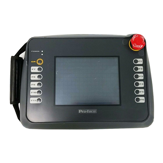
Page 36: Part Names And Functions
Chapter 2 – Specifications Part Names and Functions This section describes the name and function of each part of the GP unit. (The GP-2401H is used for the Front diagram. This unit's display panel size and number of function switches differ from those of the GP-2401H unit.) A: Display Panel A, B Displays user-created screens and corre-... - Page 37 Chapter 2 – Specifications CF Card Access LED When the CF Card Access Switch is turned ON, the LED lamp turns ON. When the CF Card Access Switch is turned OFF, the LED lamp turns OFF. However, the lamp is ON while the GP unit is accessing the CF Card.
-
Page 38: Dimensions
Chapter 2 – Specifications Dimensions 2.5.1 GP-2301H Series / GP-2401H Series External Dimensions Even though only the GP2401H-TC41-24V is shown below, the dimensions of the GP2301H-LG41-24V and the GP2301H-SC41-24V are the same. Unit: mm [in.] 253 [9.96] Side Front 75 [2.95] Rear 4-M4 Depth: 8 [0.31] GP2000H Series User Manual... -
Page 39: Cf Card Interface Guard
Chapter 2 – Specifications 2.5.2 CF Card Interface Guard Unit: mm [in.] 118 [4.65] 106 [4.17] 2-M3 Burring 13 [0.51] 93 [3.66] 2.5.3 Emergency Switch Guard Unit: mm [in.] 57 [2.24] GP2000H Series User Manual 2–16... -
Page 40: Handling And Wiring
1. Handling the GP2000H 4. Connecting the Tool Con- 2. Interface / Switch Guards nector 3. Wiring 5. CF Card Insertion and Removal Chapter 3 Handling and Wiring Handling the GP2000H This section explains cautions involved with handling the GP2000H Series units. Be sure to operate the GP unit only after securing it, using any of the following three methods. -
Page 41: Hand Strap
Chapter 3 – Attaching and Wiring 3.1.2 Hand Strap Attaching the Hand Strap The hand strap that attaches to the GP2000H Series unit is used to hold the GP unit by hand, and to prevent it from dropping during use. Attach the hand strap using the following procedure (images of the GP-2301H are used, but the proce- dure is the same for the GP-2401H): 1. -
Page 42: Neck Strap
Chapter 3 – Attaching and Wiring 3.1.3 Neck Strap Attaching the Neck Strap The neck strap that attaches to the GP2000H Series unit is used to hang the GP unit from the user’s neck, and to prevent it from dropping during use. Attach the neck strap using the following procedure (images of the GP-2301H are used, but the procedure is the same for the GP-2401H): 1. -
Page 43: Interface / Switch Guards
Chapter 3 – Attaching and Wiring Interface / Switch Guards This section explains how to install the CF Card Interface Guard and Emergency Switch Guard included in the GP2000H Series unit’s packing box. 3.2.1 CF Card Interface Guard Attaching the CF Card Interface Guard Attach the guard as follows, to meet the NEMA#250 TYPE4X/12 environment requirements. -
Page 44: Emergency Switch Guard
Chapter 3 – Attaching and Wiring 3.2.2 Emergency Switch Guard Attaching the Emergency Switch Guard Prevent the Emergency Switch from accidentally turning ON (for example, if the GP is dropped or placed upside down on a desk) by installing the Emergency Switch Guard, as follows: 1. -
Page 45: Wiring
Chapter 3 – Attaching and Wiring Wiring 3.3.1 Wiring WARNINGS To avoid an electric shock, be sure the power cord is un- • plugged from the power supply when connecting the power terminals to the GP unit. The GP2000H Series units use a DC 24V power supply. If •... -
Page 46: Cable Installation
Chapter 3 – Attaching and Wiring Serial Interface Termination Connector Resistance Switch DC 24V Interface External Output Connector Interface Connector 3.3.2 Cable Installation 1. Loosen the seven (7) cable cover attach- GP2000H unit’s Rear Face ment screws* on the rear of the GP unit. * These screws cannot be removed. -
Page 47: Gp2000H Mode / Gp-H70 Compatibility Mode
Chapter 3 – Attaching and Wiring 3. Securely attach the GP unit’s installa- tion gasket. GP2000H unit’s Gasket 4. Bend the cable to fit inside the GP unit’s cable channel, and adjust the cord guard to fit securely into the GP unit’s plastic Cable Cover’s casing. - Page 48 Chapter 3 – Attaching and Wiring GP2000H Mode GP-PRO/PBIII for Windows includes, in the GP Setup screen, a setting that enables or disables the Operation Switch. The touch panel’s input method depends on whether this switch is set to ON or OFF. When the Operation Switch setting is set to ON, touch input is available when the front Operation Switch is pressed —...
- Page 49 Chapter 3 – Attaching and Wiring Changing to GP-H70 Compatibility Mode WARNING To prevent an electrical shock, be sure to unplug the GP • unit’s power cord from the main power supply prior to attaching or detaching any connectors to or from the GP unit.
-
Page 50: Switching Dout/Buzz Output Current Direction
Chapter 3 – Attaching and Wiring Be sure that the 3-Position Enable Switch cover is securely fastened. Incorrect attachment of this cover can lead to water leakage and may result in damage of the GP unit. 3.3.4 Switching DOUT/BUZZ Output Current Direction GP2000H Series units can switch the direction of the DOUT/BUZZ output cur- rent. - Page 51 Chapter 3 – Attaching and Wiring Changing the Current Direction 1) Loosen the seven (7) Cable Cover Attachment Screws, and remove the cover. * These screws are the non-removable type. Cable Cover 2) Loosen the Stopper’s screw (1) and remove the Stopper. *This screw is the non-removable type.
-
Page 52: Tool Connector
Chapter 3 – Attaching and Wiring Tool Connector A data transfer cable can be attached to the GP unit’s tool connector. The GP unit’s tool connector is located on the right side, inside the CF Card Cover. WARNING To prevent an electrical shock, be sure to unplug the GP unit’s power cord from the main power supply prior to attaching or detaching any connectors to or from the GP unit. -
Page 53: Cf Card Installation And Removal
Chapter 3 – Attaching and Wiring CF Card Installation and Removal CAUTIONS When using the GP2000H unit and a CF Card, use the follow- ing precautions: • Prior to inserting or removing a CF Card, turn the GP unit’s CF Card Access Switch OFF, and confirm that the Access lamp is not lit, to prevent damage to or loss of the CF Card’s internal data. - Page 54 Chapter 3 – Attaching and Wiring Inserting the CF Card Use the following steps to insert the CF Card in the GP2000H unit. 1. Unlock the CF Card Cover Lock on both sides, and then slide the CF Card Cover in the specified direction, and upwards, to open the cover.
-
Page 55: Cf Card Handling
Chapter 3 – Attaching and Wiring 3.5.1 CF Card Handling The CF Card has a data overwrite limit of approximately 100,000 times. There- fore, be sure to back up all CF Card data regularly to another storage media. (100,000 times assumes the overwriting of 500KB of data in DOS format.) To view CF Card data on a personal computer, insert the CF Card into a CF Card Adapter, and then insert the adapter into your personal computer's PC card slot. -
Page 56: Chapter 4 Data Transfer
1. Serial Data Transfer 2. CF Memory Loader Tool Chapter 4 Data Transfer This chapter explains how to transfer data created with the GP screen creation software using one of the following two methods: • Transfer data between the GP and your PC via the data transfer cable. •... - Page 57 Chapter 4 – Data Transfer Transfer the logic program data from your PC via the Logic Program Development software. For details about the Logic Program Development software, refer to the Pro-Control Editor Operation Manual (included in the GP screen creation software). Transferring Data to a New GP2000H Unit Connect the GP to your PC via the data transfer cable, and then turn the GP unit ON.
- Page 58 Chapter 4 – Data Transfer During data transfer, the R and SET UP TRANSFE NOW TRANSFERRING – messages appear. When these messages disappear, the screen data PLEASE WAIT transfer is completed. You can cancel data transfer at any time using the GP screen creation software. When the screen data transfer is completed, and if you do not need to set up the GP unit, the screen designated in the setting of the...
-
Page 59: Cf Memory Loader Tool
Chapter 4 – Data Transfer CF Memory Loader Tool The GP unit allows you to transfer screen data between your PC and the GP, and to upload internal GP data to its CF Card using the CF Memory Loader Tool. When using a CF Card, be sure to turn ON the CF Card Access Switch No. -
Page 60: Data Upload And Download
Chapter 4 – Data Transfer Using the GP2000H Unit’s CF Card Startup Switches You can also use the CF Card Startup Switches on the bottom of the CF Card Slot. Turn ON (raise) Switch No. 1, and insert the CF Card with the saved CF Memory Loader Tool into the GP’s CF Card slot. - Page 61 Chapter 4 – Data Transfer UPLOAD (from GP2000H to CF Card) This feature saves all GP internal data (such as system program, communication proto- col, expansion program, screen data, and Backup SRAM data) in the CF Card as backup data. To start data upload, enter the password you designated in the screen creation software’s Transfer screen, and then touch the key.
-
Page 62: Chapter 5 Offline Mode
1. Entering OFFLINE Mode 2. OFFLINE Mode Main Menu 3. INITIALIZATION Chapter 4. SELF-DIAGNOSIS 5 OFFLINE Mode Mode provides access to the GP unit’s menu, OFFLINE INITIALIZE SELF-DIAGNO- menu, and other GP features. You will need to change the GP to Mode OFFLINE before you can use any of these features. -
Page 63: Entering Offline Mode
Entering OFFLINE Mode To initialize your GP unit, or to perform , you must first switch the SELF-DIAGNOSIS GP unit to Mode. This can be done using either of the following two (2) OFFLINE methods. 5.1.1 After Plugging in the Power Cord To enter Mode, touch the top-left corner of the screen within 10 seconds OFFLINE... - Page 64 Chapter 5 – OFFLINE Mode If a password is set in the menu’s screen, the following INITIALIZE SYSTEM SETUP screen appears before entering Mode. Enter the password, and then touch OFFLINE to enter Mode. OFFLINE Enter the default password, 1101, or the password specified in the system setup. For information about entering password numbers, see 5.3 –...
-
Page 65: Offline Mode Main Menu
Chapter 5 – OFFLINE Mode OFFLINE Mode Main Menu screen contains the following menu items: OFFLINE Mode’s MAIN MENU INI- , and TIALIZE TRANSFER SCREEN DATA SELF-DIAGNOSIS The settings for each of the following menu items must match the corresponding PLC for the GP to communicate properly. -
Page 66: Initialization
Chapter 5 – OFFLINE Mode INITIALIZATION Selecting a Menu Touch the menu item or input field to select. Entering Numbers After selecting an input field, touch the numeric touch keys located at the bottom of the screen to enter the value of the selected item. After entering each input field’s numeric value, touch the SET key to register the value. - Page 67 Chapter 5 – OFFLINE Mode After Entering All Setting Data Touch the key to write the setup data to the Internal FEPROM Touch to cancel the setup, exit the screen without saving the changes, and CANCEL return to the previous menu. •...
-
Page 68: Self-Diagnosis
Chapter 5 – OFFLINE Mode SELF-DIAGNOSIS Selecting a Sub-Menu Touch the desired menu item and the corresponding sub-menu will appear. Using the SET and ESC Keys After selecting the Self-Diagnosis item, the keys may appear at ESCAPE different times at the top of the screen. SET Key Touch the key to start the... - Page 69 Chapter 5 – OFFLINE Mode If an Error Message displays, press the bottom-left corner [1] of the panel, and then touch the bottom-right corner [2] of the panel to return to the SELF-DIAGNOSIS menu. Returning to the MAIN MENU Touch the tab to return to the screen.
-
Page 70: Chapter 6 Initializing The Gp-2301H
1. Initialization Screen PLC SETUP 2. Initialization Items INITIALIZE INTERNAL MEMORY SYSTEM ENVIRONMENT SETUP SET UP TIME Chapter SET UP I/O SET UP SCREEN 9. FONT SETTING 6 Initializing the GP-2301H The GP-2301H and GP-2401H have different Setup screens. This chapter explains initial setting items contained in the GP-2301H Series unit’s Mode screens. -
Page 71: Initialization Items
Chapter 6 – Initializing the GP-2301H Initialization Items This chapter explains the contents of the setup items listed below. INITIALIZE For information about screen operations and numeric input, see Chapter 5 – “OFFLINE Mode.” menu includes the following items: INITIALIZE INITIALIZE MEMORY SYSTEM ENVIRONMENT SETUP... -
Page 72: System Environment Setup
Chapter 6 – Initializing the GP-2301H SYSTEM ENVIRONMENT SETUP Adjustments to the GP operation environment are made within the setup screens con- tained in the menu. This menu includes the SYSTEM ENVIRONMENT SETUP SYS- TEM SETUP, SYSTEM AREA SETUP, GLOBAL WINDOW SETUP, CHARAC- screens. -
Page 73: System Area Setup
Chapter 6 – Initializing the GP-2301H PASSWORD SETUP The password setting item is used when the GP unit switches to the INITIALIZE Mode) screens. The password — a number MEMORY INITIALIZE OFFLINE between 0 and 9999 — is a security feature within the Mode, to protect the OFFLINE GP unit settings. -
Page 74: Global Window Setup
Chapter 6 – Initializing the GP-2301H When the CUR- CURRENT SCREEN NUMBER ERROR STATUS CLOCK DATA RENT, , and setting items have CHANGE SCREEN NUMBER DISPLAY ON/OFF been selected, a word address is assigned to each item, in order, as shown. In the above screen, the device address used for the SET UP OPERATION SUR- screen’s... -
Page 75: Character String Data Setup
Chapter 6 – Initializing the GP-2301H GLOBAL WINDOW Two options are available: . If you select , ignore DO NOT USE DO NOT USE the items described below. Selecting enables the following options. GLOBAL WINDOW ACCESS Use this feature to designate whether values used by the GP (such as the REGISTRA- and the values) are... - Page 76 Chapter 6 – Initializing the GP-2301H CHARACTER STRING DATA MODE (1–8) Set up the that corresponds to that of your CHARACTER STRING DATA MODE PLC, as specified in the following table. (I) Data Device Storage Order (II) Byte Storage Order (LH/HL), using single words (III) Word Storage Order (LH/HL), using double words CHARACTER STRING DATA MODE (1–8) List (I) Data Device...
- Page 77 Chapter 6 – Initializing the GP-2301H III. Word Storage Order (LH/HL), using Double Words Example characters: A B C D E F G H I J • 16-bit Device LH Order • 16-bit Device HL Order D100 D100 D101 D101 D102 D102 D103...
-
Page 78: Set Up I/O
Chapter 6 – Initializing the GP-2301H SET UP I/O This section describes the communication setup with the Host (PLC) and the configura- tion for any peripheral equipment. Following are the menu screens. SET UP I/O 6.4.1 SET UP SIO This screen controls the settings related to communication with the PLCs. Be sure to match the settings listed below with the SIO setup on the host (PLC). -
Page 79: Communication Setup
Chapter 6 – Initializing the GP-2301H COMMUNICATION INTERFACE Select one of the following options for the setting: COMMUNICATION INTERFACE • RS-232C • RS-422 (4-line) • RS-422 (2-line) When using an RS-422 cable and the Memory Link format, be sure to select the 4-line option. Refer to the GP-PRO/PBIII for Windows Device / PLC Connection Manual (included with the GP screen creation software). -
Page 80: Set Up I/O
Chapter 6 – Initializing the GP-2301H 6.4.3 SET UP I/O Set up the touch panel’s modes, and TOUCH OPERATION SYSTEM RESET adjust the Display Device settings in this screen. Depending on the GP type, these settings may vary. GP2301HL (Monochrome LCD) Setup Screen GP2301HS (STN Color) Setup Screen TOUCH OPERATION MODE Designates... - Page 81 Chapter 6 – Initializing the GP-2301H SYSTEM RESET MODE Enables or disables the display of the screen’s menu bar. When set to SYSTEM RESET ON, the menu bar will display. To Perform SYSTEM RESET To enter the mode, press the bottom-right corner of the screen SYSTEM RESET (position 1, below), and then touch the top-right and bottom-left corners (positions 2 and 3).
- Page 82 Chapter 6 – Initializing the GP-2301H • To exit the CONTRAST SETTING mode, touch anywhere on the screen, except the bottom section. • CONTRAST SETTING mode cannot be entered while wait- ing for the GP unit to start up. • CONTRAST SETTING mode can be made during RUN mode (PLC GP communication).
- Page 83 Chapter 6 – Initializing the GP-2301H SET UP LCD (GP-2301HL ONLY) To reverse the screen display colors, touch on the screen to SET UP LCD SET UP I/O change the setting from , and then touch the key. The NORMAL REVERSE display color will be reversed and the previous screen will reappear.
-
Page 84: Display Setup
Chapter 6 – Initializing the GP-2301H 6.4.4 DISPLAY SETUP Depending on the GP unit’s settings and its environment, the screen’s BRIGHTNESS display may flicker. The setting may be set too low, or the GP unit’s BRIGHTNESS surrounding environment may be either too hot or too cold. This problem does not usually occur;... -
Page 85: Expansion Serial Communication Setup
Chapter 6 – Initializing the GP-2301H 6.4.6 EXPANSION SERIAL COMMUNICATION SETUP Since GP-2301H Series unit is not equipped with an expansion serial I/F. If you have selected the [NO] for the [SERIAL I/F CHANGE] on the [COMMUNICATION PORT SETUP] screen, or "No" for the [Serial I/F Switch] settings in the GP Screen Editor (when not using the Extended SIO Script Protocol for communication), the expansion serial communication setup is not required. -
Page 86: Set Up Capture Operation
Chapter 6 – Initializing the GP-2301H 6.4.8 SET UP CAPTURE OPERATION Save the captured image of the GP unit’s screen as a JPEG file in the CF Card. Refer to the GP-PRO/PBIII for Windows Tag Reference Manual, 4.7.10 – “Screen Capture,” (included in the GP screen creation software). -
Page 87: Function Setup
Chapter 6 – Initializing the GP-2301H 6.4.9 FUNCTION SETUP This setting allows the user to enable ( ) or disable ( ) the operation switch. Activate the function by touching the OPERATION SWITCH OPERATION SWITCH setting or the display area, and touch to confirm. -
Page 88: Plc Setup
Chapter 6 – Initializing the GP-2301H PLC SETUP Set up the GP unit’s and the in this screen. Because SYSTEM AREA UNIT NUMBER 1:1 and n:1 GP connections use different settings, confirm your connection require- ments before using any settings. The following assumes that the Direct Access format is used. -
Page 89: Station Setup (N:1)
Chapter 6 – Initializing the GP-2301H RESET GP ON WRITE ERROR Designates the mode that enables you to cancel the error from the error display when the Write error occurs. 6.5.2 STATION SETUP (n:1) , required with an n:1 (multi-link) setup, checks whether data com- STATION SETUP munication is being performed correctly between the GP unit and the PLC. - Page 90 Chapter 6 – Initializing the GP-2301H For example, when four GP units — bits 0, 2, 3, and 5 — are connected, 002D (h) is written. Bit 15 Bit 0 002D (h) • Be sure to set up this data before running. •...
-
Page 91: Customize Setup (N:1)
Chapter 6 – Initializing the GP-2301H 6.5.3 CUSTOMIZE SETUP (n:1) function modifies the n:1 (multi-link) connection’s communication CUSTOMIZE method to maximize its efficiency. To perform GP PLC communication efficiently, the user should first determine whether will be the priority OPERATION DISPLAY set for the GP unit. - Page 92 Chapter 6 – Initializing the GP-2301H Speed Difference between DISPLAY Priority and OPERATION Priority When using the Mitsubishi Electric Corporation A3A PLC with consecutive ad- dresses (80 words, not including the ) at a 20ms Scan Time, the SYSTEM AREA difference in reading speed is as shown in the following graphs.
-
Page 93: Initialize Internal Memory
Chapter 6 – Initializing the GP-2301H INITIALIZE INTERNAL MEMORY This section explains how to initialize the GP unit’s internal memory (screen data), or how to initialize a CF Card inserted in the GP. Select one of the menu items, [INITIAL- IZE MEMORY], [INITIALIZE CF CARD] and [CSV DATA INDEX] selections in the [INITIALIZE MEMORY] menu. -
Page 94: Csv Data Index
Chapter 6 – Initializing the GP-2301H 6.6.3 CSV DATA INDEX Specific data-transfer CSV files (ZR*****.CSV) on the CF Card can be transferred from the CF Card directly to the PLC (filing) or from the PLC directly to the CF Card (logging). -
Page 95: Set Up Time
Chapter 6 – Initializing the GP-2301H SET UP TIME Set the GP unit’s internal clock in the SET UP TIME screen. SET UP TIME Adjust the date and time display settings in the setting item. PRESENT TIME • The GP unit’s internal clock has a slight error in accuracy. At normal operating temperatures and conditions, with the GP unit operating from its lithium battery, the degree of error is ±65 seconds per month. -
Page 96: Set Up Screen
Chapter 6 – Initializing the GP-2301H SET UP SCREEN Use this screen to enter the number of the screen that is initially displayed after startup, the character size when the is in mode, and other general screen items. GP2000H INITIAL SCREEN NO. This setting item specifies the file number of the screen that initially displays on startup. -
Page 97: Font Setting
Chapter 6 – Initializing the GP-2301H FONT SETTING FONT SETTING Selects the font type displayed on the GP unit’s screen during operation. KANJI FONT QUALITY Designates the font display quality for enlarged characters. Differences in FONT SETTINGS When FONT SETTING is set to [JAPAN] Single-byte characters will remain 8x16-dot characters when they are enlarged. - Page 98 Chapter 6 – Initializing the GP-2301H All single-byte characters — ASCII code: 21h to 7Dh, or alphanumeric HIGH (1, 2) characters (except the ^ and ‘ characters) — display as high-quality characters. • When 16x16 dots are used, the characters display as high-quality 16x16-dot characters.
- Page 99 Memo...
-
Page 100: Chapter 7 Initializing The Gp-2401H
1. Initialization Screen PLC SETUP 2. Initialization Items INITIALIZE INTERNAL MEMORY SYSTEM ENVIRONMENT SETUP SET UP TIME Chapter SET UP I/O SET UP SCREEN FONT SETTING 7 Initializing the GP-2401H The GP-2301H and GP-2401H have different Setup screens. This chapter explains initialization items performed on the Mode of the GP-2401H Series unit. -
Page 101: Initialization Items
Chapter 7 – Initializing the GP-2401H Initialization Items This chapter explains the contents of the setup items listed below. INITIALIZE For information about screen operations and numeric input, see Chap- ter 5 – “OFFLINE Mode.” INITIALIZE MEMORY SYSTEM ENVIRONMENT INITIALIZE MEMORY SETUP INITIALIZE CF CARD SYSTEM SETUP... - Page 102 Chapter 7 – Initializing the GP-2401H SYSTEM ENVIRONMENT SETUP Adjustments to the Series unit operation environment are made within the GP2000H setup screens contained in the menu. This menu SYSTEM ENVIRONMENT SETUP includes the SYSTEM SETUP, SYSTEM AREA SETUP, GLOBAL WINDOW screens.
-
Page 103: System Area Setup
Chapter 7 – Initializing the GP-2401H PASSWORD SETUP The password setting item is used when the GP unit switches to the INITIALIZE MEMORY Mode) screens. The password — a number between 0 and INITIALIZE OFFLINE 9999 — is a security feature within the Mode, to protect the GP unit settings. -
Page 104: Global Window Setup
Chapter 7 – Initializing the GP-2401H When the CURRENT SCREEN NUMBER ERROR STATUS CLOCK DATA CUR- , and setting items have RENT CHANGE SCREEN NUMBER DISPLAY ON/OFF been selected, a word address is assigned to each item, in order, as shown. In the above screen, the device address used for the SET UP OPERATION SUR- screen’s... -
Page 105: Character String Data Setup
Chapter 7 – Initializing the GP-2401H GLOBAL WINDOW Two options are available: . If you select DO NOT USE DO NOT USE ignore the items described below. Selecting enables the following options. GLOBAL WINDOW ACCESS Use this feature to designate whether values used by the GP unit (such as the REGIS- and the values) are... - Page 106 Chapter 7 – Initializing the GP-2401H CHARACTER STRING DATA MODE (1–8) Set up the that corresponds to that of your CHARACTER STRING DATA MODE PLC, as specified in the following table. (I) Data Device Storage Order (II) Byte Storage Order (LH/HL), using single words (III) Word Storage Order (LH/HL), using double words CHARACTER STRING DATA MODE (1–8) List (I) Data Device...
- Page 107 Chapter 7 – Initializing the GP-2401H III. Word Storage Order (LH/HL), using Double Words Example characters: A B C D E F G H I J • 16-bit Device LH Order • 16-bit Device HL Order D100 D100 D101 D101 D102 D102 D103...
-
Page 108: Set Up I/O
Chapter 7 – Initializing the GP-2401H SET UP I/O This section describes the communication setup with the host (PLC) and the configura- tion for any peripheral equipment. Following are the menu screens. SET UP I/O 7.4.1 SET UP SIO This screen controls the settings related to communication with the PLCs. Be sure to match the settings listed below with the SIO setup on the host (PLC). -
Page 109: Set Up Printer
Chapter 7 – Initializing the GP-2401H COMMUNICATION FORMAT Select one of the following options for the setting: COMMUNICATION FORMAT • RS-232C • RS-422 (4-line) • RS-422 (2-line) When using an RS-422 cable and the Memory Link format, be sure to select the 4-line option. Refer to the GP-PRO/PBIII for Windows Device / PLC Connection Manual (included with the GP screen creation software). - Page 110 Chapter 7 – Initializing the GP-2401H FORCE RESET MODE Enables or disables the display of the screen’s menu bar. When set to FORCE RESET ON, the menu bar will display. To Perform FORCE RESET To enter the mode (see following image), press the bottom-right FORCE RESET corner of the screen (position 1), and then touch the top-right and bottom-left corners (positions 2 and 3).
- Page 111 Chapter 7 – Initializing the GP-2401H • To exit the BRIGHTNESS ADJUSTMENT mode, touch any- where above the BRIGHTNESS ADJUSTMENT bar. • You cannot enter the BRIGHTNESS ADJUSTMENT mode while the GP unit is starting up. • BRIGHTNESS ADJUSTMENT can be made during RUN mode (PLC GP unit communication).
-
Page 112: Communication Setup
Chapter 7 – Initializing the GP-2401H 7.4.4 COMMUNICATION SETUP This section explains how to use the command to deal with errors, including RETRY those that occur during communication. RECEIVE TIMEOUT (1–127) Use a numeric value to set a period of time in which the GP unit receives data from the PLC. -
Page 113: Expansion Serial Communication Setup
Chapter 7 – Initializing the GP-2401H 7.4.6 EXPANSION SERIAL COMMUNICATION SETUP Since GP-2401H Series unit is not equipped with an expansion serial I/F. If you have selected the [NO] for the [SERIAL I/F CHANGE] on the [COMMUNICATION PORT SETUP] screen, or "No" for the [Serial I/F Switch] settings in the GP Screen Editor (when not using the Extended SIO Script Protocol for communication), the expansion serial communication setup is not required. - Page 114 Chapter 7 – Initializing the GP-2401H 7.4.8 SET UP CAPTURE OPERATION Save the captured image of the unit’s screen as a JPEG file in the CF Card. Refer to the GP-PRO/PBIII for Windows Tag Reference Manual, 4.7.10 – “Screen Capture” (included in the GP screen creation software).
-
Page 115: Function Setup
Chapter 7 – Initializing the GP-2401H 7.4.10 FUNCTION SETUP This setting allows the user to the operation switch. Activate the ENABLE DISABLE function by touching the setting or the OPERATION SWITCH OPERATION SWITCH display area, and touch to confirm. The default value is set to ENABLE DISABLE DISABLE... -
Page 116: Plc Setup
Chapter 7 – Initializing the GP-2401H PLC SETUP Set up the GP unit’s and the in this screen. Because SYSTEM AREA UNIT NUMBER 1:1 and n:1 GP connections use different settings, confirm your connection require- ments before using any settings. The following assumes that the Direct Access format is used. -
Page 117: Set Up Operation Surroundings (1:1/N:1)
Chapter 7 – Initializing the GP-2401H 7.5.1 SET UP OPERATION SURROUNDINGS (1:1/n:1) Enter the PLC and the settings in this screen. SYSTEM DATA AREA UNIT NUMBER The same options are available for both 1:1 and n:1 (multi-link) connections. For an n:1 (multi-link) connection, settings must be set up for SYSTEM DATA AREA each GP unit connected to the PLC. -
Page 118: Station Setup (N:1)
Chapter 7 – Initializing the GP-2401H 7.5.2 STATION SETUP (n:1) , required with an n:1 (multi-link) setup, checks whether data com- STATION SETUP munication is being performed correctly between the GP unit and the PLC. NETWORK INFORMATION ADDRESS With an n:1 (multi-link) connection, the setting uses two NETWORK INFORMATION (2) words —... - Page 119 Chapter 7 – Initializing the GP-2401H For example, when four GP units — bits 0, 2, 3, and 5 — are connected, 002D (h) is written. Bit 15 Bit 0 002D (h) • Be certain to set up this data before running. •...
-
Page 120: Customize Setup (N:1)
Chapter 7 – Initializing the GP-2401H 7.5.3 CUSTOMIZE SETUP (n:1) function modifies the n:1 (multi-link) connection’s communication CUSTOMIZE method to maximize its efficiency. To perform GP PLC communication effi- ciently, the user should first determine whether will be the OPERATION DISPLAY priority set for the GP unit. - Page 121 Chapter 7 – Initializing the GP-2401H Speed Difference between DISPLAY Priority and OPERATION Priority When using the Mitsubishi Electric Corporation A3A PLC, with consecutive addresses (80 words, not including the ), the difference in reading speed is as SYSTEM AREA shown in the following graphs.
-
Page 122: Initialize Internal Memory
Chapter 7 – Initializing the GP-2401H INITIALIZE INTERNAL MEMORY This section explains how to initialize the GP unit’s internal memory (screen data), or how to initialize a CF Card inserted in the GP. Select either the INITIALIZE MEMORY item or the item in the menu. -
Page 123: Csv Data Index
Chapter 7 – Initializing the GP-2401H 7.6.3 CSV DATA INDEX Specific data-transfer CSV files (ZR*****.CSV) on the CF Card can be transferred from the CF Card directly to the PLC (filing) or from the PLC directly to the CF Card (logging). -
Page 124: Set Up Time
Chapter 7 – Initializing the GP-2401H SET UP TIME Set the GP unit’s internal clock in the screen. SET UP TIME SET UP TIME Adjust the date and time display settings in the setting item. PRESENT TIME • The GP unit’s internal clock has a slight error in accuracy. At normal operating temperatures and conditions, with the GP unit operating from its lithium battery, the degree of error is ±65 seconds per month. -
Page 125: Set Up Screen
Chapter 7 – Initializing the GP-2401H SET UP SCREEN Use this screen to enter the number of the screen that is initially displayed after startup, the character size when the is in mode, and other general screen items. GP2000H INITIAL SCREEN NO. This setting item specifies the file number of the screen that initially displays on startup. -
Page 126: Font Setting
Chapter 7 – Initializing the GP-2401H FONT SETTING FONT SETTING Selects the font type displayed on the GP unit’s screen during operation. KANJI FONT QUALITY Designates the font display quality for enlarged characters. Differences in FONT SETTINGS When FONT SETTING is set to [JAPAN] Single-byte characters will remain 8x16-dot characters when they are enlarged. - Page 127 Memo...
-
Page 128: Chapter 8 Run Mode And Errors
1. RUN Mode 2. SELF-DIAGNOSIS 3. Troubleshooting Chapter 4. Error Messages 5. Error Message Details 8 RUN Mode and Errors In this chapter, the GP-2301H Series unit’s OFFLINE Mode is used in explanations for the reader’s convenience only. There is no difference in function between the GP-2301H and the GP-2401H, unless otherwise noted. -
Page 129: Via Offline Mode
Chapter 8 – RUN Mode and Errors If the initial screen’s file number is not designated, or if a number that does not exist is designated, the version information screen remains displayed. Depending on the display device’s startup time, it is possible that the screens (see diagrams, previous page) may not ini- tially be displayed. -
Page 130: Self-Diagnosis
Chapter 8 – RUN Mode and Errors SELF-DIAGNOSIS is equipped with a number of features used to check GP2000H SELF-DIAGNOSIS its System and Interfaces for any problems. 8.2.1 SELF-DIAGNOSIS ITEM LIST GP-2301H Series GP-2401H Series GP2000H Series User Manual 8–3... - Page 131 Chapter 8 – RUN Mode and Errors 1. CHARACTER PATTERN A. PRINTER I/F Checks the characters inside the inter- B. SIO CHECK nal Character ROM. Checks the RS-232C and RS-422 2. DISPLAY PATTERN send/receive lines. Checks all the figures and tiling patterns. C.
-
Page 132: Self-Diagnosis - Details
Chapter 8 – RUN Mode and Errors 8.2.2 SELF-DIAGNOSIS – Details This section explains the contents of the menu. SELF-DIAGNOSIS For information on how to operate the menu interface, see Chapter 5 – “ Mode.” OFFLINE For information on how to set up the Special Tools, see Chapter 3 – “Handling and Wiring.”... - Page 133 Chapter 8 – RUN Mode and Errors 5. INTERNAL FEPROM CHECKSUM (System and Protocol) The Internal System and Protocol check searches for any problems that FEPROM may occur during operation. When running the check, the screen changes as follows: When the is normal, OK displays.
- Page 134 Chapter 8 – RUN Mode and Errors A. PRINTER I/F cannot be performed, since the Series unit does not SELF-DIAGNOSIS GP2000H have the Printer Interface. B. SIO CHECK Checks the RS-232C and RS-422 SIO lines for areas where communication problems develop. In the menu, select which check to run. To run the check, connecting the SIO cable is necessary.
- Page 135 Chapter 8 – RUN Mode and Errors E. SOUND I/F cannot be performed, since the Series unit does not SELF-DIAGNOSIS GP2000H have the Sound Interface. F. CF CARD MEMORY LOADER FILE CHECK Checks the CF Card’s Memory Loader Tool when it does not start. If no error exists, the message OK will appear.
-
Page 136: Troubleshooting
Chapter 8 – RUN Mode and Errors Troubleshooting This section explains how to find and resolve the following problems, which may occur while using the GP unit. If a problem exists with the PLC, refer to the corresponding PLC manual. 8.3.1 Possible Types of Trouble The following items are problems that may occur while using this unit. -
Page 137: No Display
Chapter 8 – RUN Mode and Errors 8.3.2 No Display Follow the flowchart below when the screen does not display when powering up, or the screen turns OFF by itself during RUN mode, to find an appropriate solution. No Screen Display Transfer screen data from the screen editing software. - Page 138 Chapter 8 – RUN Mode and Errors Does turning the power ON one more time start the display? Is the Status LED’s orange light The SIO cable turned ON? may not be connected The backlight is nearly burnt properly. out. Replace the backlight. Is the If the problem continues SIO cable, AUX cable...
- Page 139 Chapter 8 – RUN Mode and Errors Backlight Off data been written to the SYSTEM Erase the data that has been written. DATA AREA? When using Direct Access, the address is +14; when using Memory Link, the address is 11. For details on the SYS- , refer to the...
-
Page 140: No Gp / Host Communication
Chapter 8 – RUN Mode and Errors 8.3.3 No GP / Host Communication When the GP unit will not communicate with the host PLC, follow the flowchart below to find both the cause of the problem and a suitable response. Or, if an error message displays on the screen, check the error code to find the appro- priate solution. - Page 141 Chapter 8 – RUN Mode and Errors Are the Is the corresponding SIO INITIALIZE SELF-DIAGNOSIS / SIO CHECK settings OK? There is a problem with the GP unit. Contact your local GP distributor. Enter correct settings and values. See Chapter Are all Tags 6 / 7 –...
-
Page 142: Touch Panel / Function Key Does Not Respond
Chapter 8 – RUN Mode and Errors 8.3.4 Touch Panel / Function Key Does Not Respond When the touch panel does not respond, or its response time is very slow after it is pressed, use the flowchart below to find the origin of the problem and the appropriate solution. -
Page 143: Buzzer Sounds When Gp Power Is Turned On
Chapter 8 – RUN Mode and Errors 8.3.5 Buzzer Sounds when GP Power is Turned ON If the internal buzzer sounds when you start the GP unit, use the following chart to find the reason and the appropriate solution. Buzzer Timing Reason Solution... -
Page 144: Clock Settings Cannot Be Entered
Chapter 8 – RUN Mode and Errors 8.3.6 Clock Settings Cannot be Entered This problem occurs when the lithium backup battery's voltage, used for the internal clock, runs out. To enter the clock settings, please read the CLOCK SET UP ERROR directions. -
Page 145: Error Message List
Chapter 8 – RUN Mode and Errors Error Message List (cont.) Error Message Problem Countermeasure The communication cable was Turn the GP unit OFF and then disconnected while the GP unit ON again. was ON. The GP unit is powered OFF, RECEIVE DATA ERROR Turn the GP unit OFF and then then ON during communication... -
Page 146: Error Message Details
Chapter 8 – RUN Mode and Errors Error Message List (cont.) D-Script settings (data) are D-SCRIPT ERROR (***) incorrect. 8.5 Error Message Details Global D-Script settings (data) GLOBAL D-SCRIPT ERROR (***) are incorrect. 8.5 Error Message Details Extended SIO script settings EXTENDED SIO SCRIPT ERROR (***) (data) are incorrect. - Page 147 Chapter 8 – RUN Mode and Errors When the Changes to Mode during Mode OFFLINE When the unit changes to Mode without the user first pressing the screen, OFFLINE there is a possibility that the screen data has been damaged. In this case, after the displays, the screen automatically reverts to Mode after SYSTEM ERROR...
-
Page 148: Illegal Address In Screen Data
Chapter 8 – RUN Mode and Errors 8.5.2 Illegal Address In Screen Data Caused by an overlap of addresses. Following the error message, error codes (see below) will appear. If the error cannot be fixed, report the error code and details on how the error developed to your local GP distributor. -
Page 149: Plc Com. Error
Chapter 8 – RUN Mode and Errors 8.5.3 PLC COM. Error Appears when the address setup for tags exceeds the address range used in the host (PLC). Check the Error Number that appears and use the following table to solve the problem. -
Page 150: Clock Setup Errors
Chapter 8 – RUN Mode and Errors • With the Hitachi HIDIC H (HIZAC H) Series, the error code is divided into 2 bytes, whereas the GP Error Number is composed of 1–byte codes. Reply Return Display E.g. Command Code Error No. When the Display Error Number is 8* or 5*, use only the left column as the error number. -
Page 151: Screen Tag Limit Exceeded (384 Max.)
Chapter 8 – RUN Mode and Errors 8.5.5 Screen Tag Limit Exceeded (384 max.) When tags are set up beyond the tag limit, all tags in excess of number 384 will be disabled. Also, when tags involve registered Windows and loaded screens, they are disabled in this order: Window Registry, Load Screen. -
Page 152: Extended Sio Script Error
Chapter 8 – RUN Mode and Errors 8.5.8 Extended SIO Script Error The following error message is displayed when an Extended SIO Script is not correctly set up. The GP-2301H/2401H Series unit displays the error message at the bottom of the GP screen. - Page 153 Memo...
-
Page 154: Chapter 9 Maintenance
1. Regular Cleaning 2. Periodic Check Points 3. Changing the Backlight Chapter 9 Maintenance Regular Cleaning 9.1.1 Cleaning the Display When the surface or the frame of the display gets dirty, soak a soft cloth in water with a neutral detergent, wring the cloth tightly, and wipe the display. •... -
Page 155: Replacing The Backlight
Chapter 9 – Maintenance Replacing the Backlight The GP2000H Series unit backlights are NOT user replaceable. If backlight replacement is required, please contact your local distributor. When the unit’s backlight burns out, the unit’s status LED will turn orange. If the menu’s feature OFFLINE... -
Page 156: Index
Index Index CF Card 3–5 Numeric Access LED 2–15 3-Position Enable Switch 2–10, 2–15 Access Switch 2–15, 3–15 BOOT Program 4–5, 8–16 Cover 3–13 About the GP Unit's Display Panel Data Backup 3–16 Access Lamp 3–15, 3–16 Data Overwrite Limit 3–16 Access Token 6–1, 7–1... - Page 157 Index EXP. SERIAL I/F Check 8–10 EXPANSION SERIAL I/F Check 8–10 Damages, Losses, or Third-Party Claims 1, 15 Extended SIO Script Error 8–25 Data Device Storage Order 6–7, 7–7 External Interface Specifications 2–7 DATA FORMAT Setting 6–7, 7–7 External Interfaces 1–5 DATA LENGTH 6–16, 7–14 External Interfaces (opt.) 1–5...
- Page 158 Index I/O Setup 7–11 neck strap 3–1 I/O Setup Screens 6–9, 7–9 Neck Strap (opt.) 1–6 INITIAL SCREEN NO. Setting 6–27, 7–26 NETWORK INFORMATION ADDRESS Initialization 5–5, 6–1, 6–24, 7–1 6–20, 7–19 CF Card 6–24 NETWORK INFORMATION ADDRESS Setting INITIALIZE Menu Screens 6–2, 7–3 6–20, 7–19 Initializing the GLC 7–23...
- Page 159 Index Using the GP2000H Unit's CF Card Startup Switches 4–5 Using the SET and ESC Keys 5–7 Validation List 6–22, 7–21 Validation List Bit Numbers 6–22 Version Information Screen 8–1 VESA Compliance 3–1 VIBRATION Check8–10 Video Electronics Standards Association 3–1 Video Electronics Standards Association (VESA) 3–1 Wall Mount Adapter...
Need help?
Do you have a question about the Pro-Face GP2000H Series and is the answer not in the manual?
Questions and answers