Table of Contents
Advertisement
Quick Links
Advertisement
Table of Contents

Related Manuals for axing OTX 1310-10


Summary of Contents for axing OTX 1310-10
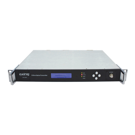
- Page 1 OTX 1310-10 Optical Transmitter Operation Instructions...
-
Page 2: Table Of Contents
4.5. Change password ............................12 Troubleshooting ..............................13 Specification...............................14 6.1. Optical characteristics ..........................14 6.2. RF characteristics ............................14 6.3. Other characteristics ..........................14 6.4. Outlines Drawing ............................15 2017-10-03 | © AXING AG Switzerland | Technical data are subject to change, errors and omissions excepted... - Page 3 Safety instructions ∂ The core part of OTX 1310-10 is a ESD laser. ∂ Please obey the operation rule strictly and carefully when disassemble and assemble. The wrist belt and the union suit should be also grounded. ∂ All electric power and optical transmitter should be given a good grounding connection.
-
Page 4: Description
Furthermore, it has two redundant plug-in power supply modules. OTX 1310-10 is used for long-distance optical fiber transmission of television TV signals. It uses a high- performance DFB laser and RF power automatic processing technology, which assures excellent performance. It can be used for large-scale HFC networks. -
Page 5: Front And Rear Panel
2. Front and rear panel 2.1. Operating elements on the front panel 1. LCD Display ∂ Output power P(mW) ∂ Laser BIAS (mA) ∂ Laser Temperature T (℃) ∂ COOL CURRENT (mA) ∂ Power supply +24.4V, +5.4V, -5.4V’s Voltage detecting ∂... -
Page 6: Connectors On The Rear Panel
Operation Instructions | OTX 1310-10 | Optical Transmitter 2.2. Connectors on the rear panel 1. RF Input Port 2. Grounding 3. RJ45 Web Management Interface 4. RS-232 5. Output Optical Connector 6. Fans 7. Power Supply Two 8. Power Supply One... -
Page 7: Installation
3. Installation Check and make sure that the equipment, enclosure and electric power have a good grounding connection. Check and make sure that the electric power is within 90…265VAC. Connect the optical fibre with the optical output. Make sure the connection is cleanded before use. Connect the electric power and turn on the power switch. -
Page 8: Menu Interface
Operation Instructions | OTX 1310-10 | Optical Transmitter 3.1. Menu Interface Press System RF Menu Press RF Gain RF Gain Press Mode Mode Press OMI Level Level Normal Optical Attenuation Adjust Press Attenuation Adjust RF Menu Adjust Attenuation System Main... - Page 9 System Menu Optical Menu Laser Power Firmware Version V1.0 10.5mW Laser Bias Current Series Number 53mA Laser Temp System Temp 25.3℃ 32℃ Laser Cool Current Power1 +24.4V +24.4V +100mA Power1 +5.4V Optical Wave Length +5.4V 1310.00nm Power1 -5.4V -5.4V 192.168.1.1 GATE WAY Power2 +24.4V 192.168.1.1...
-
Page 10: Web Management
Operation Instructions | OTX 1310-10 | Optical Transmitter 4. WEB Management Enter 192.168.1.1 into your web browser to get the following web interface. The default password is admin After the login, 5 items are displayed on the web interface: ∂... -
Page 11: Settings
4.2. Settings The parameters, which are displayed here can be changed: AGC and MGC mode can be selected. RF Attenuation from 0~12dB can be set , when MGC mode is activated OMI can be set from -5~5dB 4.3. Information Here general information about the model, serial number, firmware version, SNMP private OID, admin contact, system name and location are displayed. -
Page 12: Network Configuration
Operation Instructions | OTX 1310-10 | Optical Transmitter 4.4. Network configuration Here the following parameters according to customer network can be set. 4.5. Change password Here the password can be changed. The default password is admin. 2017-10-03 | Technical improvements, changes in design, printing- and other errors expected. -
Page 13: Troubleshooting
5. Troubleshooting General Recovery Processing Failure Phenomenon Reason Settle Method no electric power or fuse LED does not work Power ON or Fuse replace burn out Temperature maybe too LED is black Force Cooling high The measurement of the output laser power is not LED displays the status is normal, correct. -
Page 14: Specification
Operation Instructions | OTX 1310-10 | Optical Transmitter 6. Specification 6.1. Optical characteristics Parameter Unit Value Working Wavelength 1290~1330 Output Power Optical Fiber Type Optical Connector SC/APC 6.2. RF characteristics Parameter Unit Value Frequency Range 47…1002 RF Input Return Loss ≥16... -
Page 15: Outlines Drawing
6.4. Outlines Drawing Dimensions are in mm. 2017-10-03 | Technical improvements, changes in design, printing- and other errors expected. - Page 16 Operation Instructions | OTX 1310-10 | Optical Transmitter 2015-12-04 | © AXING AG Swizzerland | Technical data are subject to change, errors and omissions excepted...
Need help?
Do you have a question about the OTX 1310-10 and is the answer not in the manual?
Questions and answers