Advertisement
CLOCK INPUT & TAP TEMPO
1
In addition to producing a programmable, internal clock source on it's own,
GateStorm will accept external clock sources via the CLOCK input jack or
CV bus. BPM can be set via the system controls and updates via system
parameter settings and the TAP tempo button to the right of the input.
Clock sample resolution is adjustable via PRESET/GLOBAL settings, pg 6.
LOCAL TRIGGER INPUTS 1-4
2
The four Local Trigger inputs are for triggering events associated with the
complex sequence lanes 1 through 4. For example, to trigger a one shot on
complex lane 2, a trigger signal would be patched into TRIG 2 and so forth,
See pg 5 for more info.
GLOBAL TRIGGER INPUTS 1-2
3
The two Global Trigger inputs are for triggering system wide events within
GateStorm. G-TRIG 2 also features a normalized button for triggering
changes manually. Global Trigger parameters are adjustable within the SEQ
lanes and GLOBAL menus.
CONTROL VOLTAGE INPUTS 1-6
4
The six Control Voltage inputs are provided for modulating the parameters of
just about every function of GateStorm. The associated potentiometer
controls, described below, adjust the depth of the incoming control voltage
signals. A 5V DC signal is normalized to all the inputs for controlling
GateStorm functions via the CV potentiometers, when no signals are
patched into these jacks. See pg 4 for more info.
CONTROL VOLTAGE POTENTIOMETERS 1-6
5
The six Control Voltage pots are provided for manually changing the assigned
parameters of GateStorm. As mentioned above, a 5V DC signal is normalized to all
the inputs for controlling GateStorm functions via the CV potentiometers when no
signals are patched into the numerically related CV input jacks. If a signal is applied
to a CV input jack, the related control pot is used as an attenuator for that signal.
GATE OUTPUTS A-H
6
These are the eight Gate Outputs of GateStorm. By default, the complex and simple lane
outputs are mapped in order of 1-8 to outputs A-H. Since all the lanes are re-mappable,
rotatable etc., the letter naming convention is utilized to distinguish between the lane and
assigned output jack. The current lane output jack is denoted on the right side of the main
screen next to the lane number for each sequence lane.
NAVIGATION ENCODER
A
This is the control used for navigation within the system including the selection of each lane and variation of local and global parameters within the system. Pushing this control will also cycle onto the preset and system pages.
B
MAIN MENU/PARAMETER BUTTONS
These are direct access buttons to the essential functions of GateStorm. From sequence settings to CV mapping and global functioning, these controls are described in more detail on the following pages of the manual.
C
STEP/SELECTION BUTTONS
D
The buttons numbered 1-8, below the display are used for programming the complex lane steps as seen in the module image above, and for selecting speci c parameters within the di erent sections of GateStorm. When
selecting a speci c function within a page, the numbered button corresponds with the position of that function on the bottom of the display, above the numbered buttons. The display will only show what features are available
in the current page menu.
DISPLAY
E
This where everything that happens within GateStorm is visible. Details of the display are described on the following pages of the reference manual. A quick description of the
main lane/sequence page is provided, below.
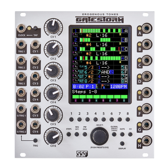
COMPLEX LANES 1-4
From left to right is the lane number in blue, active steps is green with numbers (shown in lane 1) to denote selected steps for modi cation, lane number and mapped output letter. Below
is Pulse Width (purple) and associated pulse length waveform in white and Sync active indicator below. The arrow denotes the clock direction (forward, backward and pendulum). In orange
is the clock multiplication (* )and division (/) indicator, followed by the lane seq length (L). The Box to the immediate right indicates which functions are currently active for each lane.
SIMPLE LANES 5-8
From left to right are the Pulse Width (purple) and associated pulse length waveform in white and Sync active indicator below. Clock and Random density in cyan. The next box to the right
indicates the selected lane in cyan and multiplication (*) and division (/) value for that input. The next box is the logic section and indicates the rst lane selected, logical operator in white
(arrow indicates direct output [no logic]) and then the second lane input. A box around the number indicates that the lane output has been inverted. The next section to the right (nothing
shown) indicates active options for each lane. Finally we see the lane number and mapped output letter.
BANK/PRESET, CV and CLOCK
This small strip in blue shows the current and bank and preset number. CV level and dynamics are show for the six CV controls, ordered 1-6 (top to bottom) as colored bars. The next box
shows active clock settings and to the right is the current tempo in beats per minute.
PAGE/MENU and PARAMETERS
The current menu, selectable by the direct menu buttons is shown is white. Below are the available options for each respective page/menu, selectable via the numbered buttons below the
display. In this case we see the active steps for 1-8 (of 16).
E R O G E N O U S
T O N E S
1
2
3
GATESTORM
Control and function reference guide
5
4
B
E
D
A
C
{
{
{
{
6
Advertisement
Table of Contents

Summary of Contents for SSF Erogenous Tones GATESTORM
- Page 1 GATESTORM E R O G E N O U S T O N E S Control and function reference guide CLOCK INPUT & TAP TEMPO In addition to producing a programmable, internal clock source on it’s own, GateStorm will accept external clock sources via the CLOCK input jack or CV bus.
- Page 2 GateStorm might look complicated, however, the UI is laid out to be fast and straightforward once you learn all the features and functions at your disposal This short guide is just provided as a quick overview, we recommend viewing the videos at the Erogenous Tones website to become familiar with how GateStorm Works (http://erogeous-tones.com) or (http://steadystatefate.com) INTRO GateStorm is what we like to call an advanced gate generator The concept behind GateStorm was exibility, especially for performances This is why GateStorm includes a patch system.
- Page 3 The PW button has 3 menus under it as well, pulse widths and random settings. In addition, the Random Constraint System has sub pages for constraining the random features. PW Page 1 PULSE WIDTHS Each channel stores its own pulse width settings. The pulse width settings a ect every step the same. You can manually select the pulse width or chose from a few prede ned values. For Complex Lanes, setting a pulse width of 1 will tie steps together.
- Page 4 The third page is the TRANSPORT page. The entire system provides a few di erent ways for gates to be started and stopped. When the transport is stopped or paused, the area behind the BPM will be colored red. Complex and Simple tracks that have been setup to use the GPLAY signal will stop when the transport stops.
- Page 5 SIMPLE CV For the Simple LANE CV settings, the CV controls work the same as the complex in terms of how they are programmed in. Here you can CV control the Source 1, Source 2, Logic setting, Time Base, Pulse Width and the clock density of the simple lane.
- Page 6 For the complex lanes we have three columns of trigger information, Play (>), Random (?) and Reset (R): Play: The top of the 3 bars represents LPlay, and the color will correspond to the lane (Like, yellow is lane 1). The second bar indicates the play state of the global play. When global play control is con gured properly for this lane, a green or red box will be shown in the second spot.
- Page 7 On the second page of the SYSTEM SETTINGS is the color and rmware version (note the rmware version also shows in the awesome intro animation). You can cycle through a variety of colors for both the steps and the wiper line. Use Read to replace any changes you have made with what is saved into memory.
Need help?
Do you have a question about the Erogenous Tones GATESTORM and is the answer not in the manual?
Questions and answers