
Related Manuals for DigiTrak F5 SST

Summary of Contents for DigiTrak F5 SST
- Page 1 ® Guidance System Operator’s Manual IGITAL ONTROL dci@digital-control.com NCORPORATED www.DigiTrak.com...
- Page 2 Limited Warranty and the FCC’s authorization to operate the equipment. CE Requirements DigiTrak receivers are classified as Class 2 radio equipment per the R&TTE Directive and may not be legal to operate or require a user license to operate in some countries. The list of restrictions and the required declarations of conformity are available on DCI’s website, www.digitrak.com, under the...
- Page 3 India DTJ 1023, 10th Floor DLF Tower A, DA District Center Jasola, New Delhi 110044 +91.11.4507.0444 +91.11.4507.0440 fax dci.india@digital-control.com Russia Molodogvardeyskaya Street, 4 Building 1, Office 5 Moscow, Russia 121467 +7.499.281.8177 +7.499.281.8166 fax dci.russia@digital-control.com ® ® ® Operator’s Manual DigiTrak...
- Page 4 NCORPORATED Dear Customer, Thank you for choosing a DigiTrak locating system. We are extremely proud of the equipment we have been designing and building in Washington State since 1990. We believe in providing a unique, high-quality product and standing behind it with superior customer service and training.
-
Page 5: Table Of Contents
Editing and Annotating Charts ......................45 Printing and Previewing Project Files ....................47 Saving Project Files ..........................47 E-mailing Report to Customer Who Does Not Have DigiTrak LWD software ........48 INPUTTING AND EDITING DRILL DATA ....................49 Topography ............................49 Drill Plan ............................... -
Page 6: Safety Precautions And Warnings
NCORPORATED Safety Precautions and Warnings Carefully review this manual and be sure you always operate your DigiTrak locating system properly to obtain accurate depth, pitch, roll, and locate points. If you have any questions about the operation of the system, please contact DCI Customer Service for assistance. -
Page 7: Equipment And Battery Disposal
Pre-Drilling Testing Before each drilling run, test your DigiTrak locating system with the transmitter inside the drill head to confirm it is operating properly and providing accurate drill head location and heading information. -
Page 8: Interference
Reorient or relocate the receiving antenna. Increase the separation between the receiver and affected equipment. Consult the dealer, DCI, or an experienced radio/TV technician for help. Connect the DCI equipment to an outlet on a different circuit. ® ® ® Operator’s Manual DigiTrak... -
Page 9: Introduction
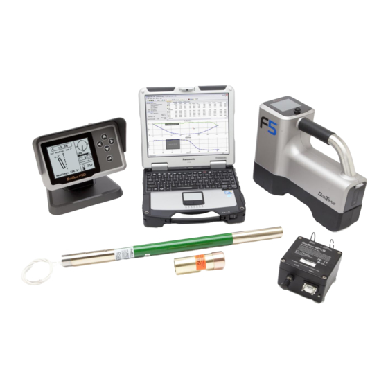
DCI recommends that you use a combination of walkover and non-walkover locating whenever possible to increase the capabilities and accuracy of the SST system. A standard F5 system can be upgraded to the F5 SST system. ®... - Page 10 This operator’s manual begins by describing the primary System Components—including the SST transmitter, the F5 SST receiver, the SST remote display, the multi-function cable box (MFCB), and the laptop computer with preinstalled LWD (Log-While-Drilling) software—and the other supplies needed for ®...
- Page 11 You also must read the instructions given in this SST system operator’s manual and familiarize yourself with the various menu screens on your F5 SST receiver and remote display before using the system for a production drill. We also recommend that you review the LWD software application and the help files in the software relating to the SST (steering tool) guidance system.
-
Page 12: System Components
IGITAL ONTROL NCORPORATED System Components The F5 SST guidance system consists of the following main components, which are described in this section: SST transmitter – A cable transmitter with an internal compass; requires protective magnetic shield. F5 SST receiver – An F5 receiver upgraded with the SST capability. -
Page 13: F5 Sst Receiver
SST Transmitter Housing Slot Requirements F5 SST Receiver The F5 SST receiver is an F5 receiver that has been upgraded with the SST capability. The receiver is used to locate the SST transmitter when walkover locating is possible and to confirm depth readings and other transmitter data. -
Page 14: Sst Remote Display
The SST remote display is a multi-function remote that receives and displays real-time information including heading, pitch, roll, temperature, and battery status. Any DigiTrak F Series Display (FSD) or DigiTrak Multi-Function Display (MFD) can be upgraded to have the SST capability. -
Page 15: Multi-Function Cable Box (Mfcb)
See the LWD Software Instructions section for more information. Cable for Panel-Mounted MFD Remote Complete information and procedures for setting up the SST system and connecting the system components is given in the System Oper- ating Instructions section. ® ® ® Operator’s Manual DigiTrak... -
Page 16: Laptop Computer With Lwd Software
System Components Laptop Computer with LWD Software The F5 SST system comes with a dedicated laptop computer (PC) that has the LWD (Log-While-Drilling) software preinstalled. A 50-ft (15-m) long serial cable is provided for connecting the computer to the serial port on the cable box. -
Page 17: Non-Dci Components That Are Needed
Tape measure 12–28V DC battery or power supply Amp meter Digital level Compression fitting – Required to seal the transmitter from drilling fluid; contact a drill or tooling manufacturer for information. ® ® ® Operator’s Manual DigiTrak... -
Page 18: System Operating Instructions
3. Assemble and Torque-up Non-Magnetic Housing to Non-Mag Tool Using the drill rig or other hydraulic torquing wrenches, thread the non-mag housing to the non-mag tool and torque-up. ® ® ® Operator’s Manual DigiTrak... - Page 19 Be sure there are no large metallic objects, in- cluding the drill, within 30 ft (9 m) of the non-mag assembly. Aligning Non-Mag Tooling Assembly to Marked Bore Path ® ® ® Operator’s Manual DigiTrak...
- Page 20 6. Stage SST Equipment and Power Source Adjacent to Tooling Assembly In preparation for powering up the F5 SST equipment, position the following items adjacent to the tooling assembly, along with the required cords, cables, and supplies for connecting the components: ...
- Page 21 Operating Instructions 7. Connect and Power Up F5 SST Equipment First, install the battery pack in the receiver, and then click the trigger to power it up. From the main menu, go to the transmitter selection menu and select the cable option, and then the SST transmitter option.
-
Page 22: Setting Reference Heading And Roll Offset
The receiver’s locate mode screen also displays the heading of the SST transmitter. Keypad option for manual input of reference heading Set option shows current SST transmitter heading SST Remote Popup Menu for Establishing Reference Heading ® ® ® Operator’s Manual DigiTrak... - Page 23 SST transmitter is off from the reference heading, as shown below. Offset of SST Reference transmitter heading heading from reference heading SST Remote Steering Screen Showing Heading 4.7° to Left of Reference Heading ® ® ® Operator’s Manual DigiTrak...
- Page 24 0°, and the roll offset value (194° in this example) will appear below the letters “RO” on the lower right of the roll indicator, as shown below. Drill head roll position and value Roll offset value SST Remote Steering Screen Showing New Roll Offset Value ® ® ® Operator’s Manual DigiTrak...
- Page 25 Option menu on the receiver. The roll offset menu will display, as shown below. Disable roll offset Set and enable Exit (returns to roll offset (shown settings menu) highlighted) SST Receiver Roll Offset Menu ® ® ® Operator’s Manual DigiTrak...
- Page 26 The roll offset function will be disabled and the value of the roll shown on the receiver will be that of the SST transmitter. ® ® ® Operator’s Manual DigiTrak...
-
Page 27: Calibrating Sst Transmitter And Confirming Proper System Operation
Check signal strength by selecting the locate mode from the receiver’s main menu screen. Position the receiver 10 ft (3 m) to the side of the SST transmitter in the non-mag housing, as shown in the figure below. F5 SST 10 ft (3 m) transmitter... - Page 28 Connect the cable box to the serial port on the laptop computer using the serial cable provided with the system. The laptop can be positioned as far as 50 ft (15 m) from the drill. ® ® ® Operator’s Manual DigiTrak...
- Page 29 Steering Tool Data Upload Control dialog box shown below. Serial port pull- down options Connect to device button Select to open help wizard Steering Tool Data Upload Control Dialog Box (not connected) ® ® ® Operator’s Manual DigiTrak...
- Page 30 Steering Tool Data Upload Control Dialog Box (connected) See the Inputting and Editing Drill Data section later in this manual for complete information on using the job information and data upload control dialog boxes. ® ® ® Operator’s Manual DigiTrak...
-
Page 31: Logging Drill Run
It can also be edited after logging by using the Edit Steering Tool Data Point dialog box described below. See the Inputting and Editing Drill Data section for more information. ® ® ® Operator’s Manual DigiTrak... - Page 32 To adjust the recorded bore path based on externally measured data, use the confidence points tab in the data tables area of the main application window. Topography must be input in order to use confidence points. See the Inputting and Editing Drill Data section for more information. ® ® ® Operator’s Manual DigiTrak...
- Page 33 NOTE: Be careful to be methodical when pulling back and advancing rods so that you do not hit the button more times than the number of rods pulled back or advanced. ® ® ® Operator’s Manual DigiTrak...
- Page 34 Then, if you accidentally make changes you don’t want, you can still revert to the earlier version of the file. You may even want to save the drill data more than two times. ® ® ® Operator’s Manual DigiTrak...
-
Page 35: Summary Of Basic Operating Procedure
5. Position and align non-mag tooling assembly onto marked bore path. 6. Stage SST equipment and power source adjacent to tooling assembly. 7. Connect and power up F5 SST equipment. 8. Measure SST transmitter current draw. 9. Install SST transmitter into aligned non-mag tooling assembly. -
Page 36: Lwd Software Instructions
The LWD (Log-While-Drilling) software, which is preinstalled on the SST laptop computer, is used with the F5 SST guidance system. The SST transmitter is referred to as the “steering tool” in the LWD software. There are three ways to start the DigiTrak LWD program: ... - Page 37 Click on the tool tip helper icon on the tool bar and click on a point of interest within the file to open a help window with information about the point of interest. ® ® ® Operator’s Manual DigiTrak...
-
Page 38: Menu And Tool Bars
Launches or hides the Steering Tool Data Upload Control dialog box where Control… you can link to the cable box and view and record steering tool data. File 1, 2… Opens the specified previously opened file. Exit Exits DigiTrak LWD program. ® ® ® Operator’s Manual DigiTrak... - Page 39 LWD applications, such as the Pressure-Tension and the Drill DataLog applications. View Menu Commands Toolbar Shows or hides the tool bar. Status Bar Shows or hides the status bar. Bluetooth Shows a list of registered Bluetooth devices. Device List… ® ® ® Operator’s Manual DigiTrak...
-
Page 40: Information Fields
Help Menu Commands Help Topics Offers you an index to topics on which you can get help. About Displays the version number of the DigiTrak LWD software. DigiTrak LWD... Information Fields The steering tool application in the LWD software displays information grouped in related fields as discussed briefly below. - Page 41 Hdg.Dev. – Calculated deviation from the reference heading in degrees recorded at the specified data point. Dist. – Calculated aboveground distance the SST transmitter has traveled from the drill rig up to that data point. ® ® ® Operator’s Manual DigiTrak...
- Page 42 Course R/L – Distance right, R, or left, L, from the reference heading line to the specified drill plan point on the plan view chart. Units are those displayed in the job information field for depth. ® ® ® Operator’s Manual DigiTrak...
- Page 43 (control-click) on your mouse while you drag the pointer through the area you wish to explode. Release the mouse button once the area is selected. To return the chart to its normal scaling, control-click anywhere in the chart area. ® ® ® Operator’s Manual DigiTrak...
- Page 44 (L) is a positive value. Cursor coordinate details appear when you hover the mouse over the plan view chart, and data point details appear when you hover the mouse over a data point in the chart. ® ® ® Operator’s Manual DigiTrak...
-
Page 45: Editing And Annotating Charts
Hold the shift key down and use the mouse to draw a box around the area you would like a shape to appear on the chart. The Location area of the dialog box will automatically be filled with the coordinates of the box you drew. Profile Chart Annotation Dialog Box ® ® ® Operator’s Manual DigiTrak... - Page 46 Automatic scaling is selected by default. Click in the box next to “Auto Scale” to adjust the horizontal or vertical scaling and chart boundaries. Then manually enter the coordinates of chart boundaries as you would like them to appear. ® ® ® Operator’s Manual DigiTrak...
-
Page 47: Printing And Previewing Project Files
Save button. The open file will now have the new file name and/or location. DCI recommends saving each job file with two different names in the event that one file becomes corrupted. ® ® ® Operator’s Manual DigiTrak... -
Page 48: E-Mailing Report To Customer Who Does Not Have Digitrak Lwd Software
E-mailing Report to Customer Who Does Not Have DigiTrak LWD software The DigiTrak LWD software is able to generate a printed report or an electronic copy of your file, as discussed above under “Printing and Previewing Project Files.” In addition, electronic project files can be sent to and opened by anyone who has the DigiTrak LWD software. -
Page 49: Inputting And Editing Drill Data
2. Right-click on the highlighted point in the data list and select Edit or double-click on the point in the list or on the terrain graph to open the Edit Topo Data dialog box. Edit Topo Data Dialog Box ® ® ® Operator’s Manual DigiTrak... - Page 50 Terrain Survey Data… A Windows Explorer dialog box will display. 2. Locate and select the CSV file previously saved and click on Open. The topography data table will populate and the profile view chart will show the green terrain graph. ® ® ® Operator’s Manual DigiTrak...
-
Page 51: Drill Plan
1. Right-click in any blank cell in the drill plan data table and select Insert. A new plan point will display in the data table and on the chart with default depth, relative elevation, and course deviation values. 2. Edit the drill plan data values, if necessary. ® ® ® Operator’s Manual DigiTrak... - Page 52 2. Right-click on the highlighted point in the list and select Delete. The plan point will be deleted and the graph will adjust to connect the data points before and after the one that was deleted. ® ® ® Operator’s Manual DigiTrak...
- Page 53 2. Locate and select the CSV file previously saved and click on Open. The drill plan data table will populate, and the profile and plan view charts will populate with all entered data including the gray line representing the drill plan graph. ® ® ® Operator’s Manual DigiTrak...
-
Page 54: Confidence Points
2. Right-click on the highlighted point and select Delete. The confidence point will be deleted from the graph and data table. The graph will display the original calculated value for depth. ® ® ® Operator’s Manual DigiTrak... -
Page 55: Job Information
If the drill enters the ground at some distance left, L, or right, R, of where the reference heading was set, enter the lateral distance of the offset next to “Lat. Offset At Entry” (5 R in the example above). ® ® ® Operator’s Manual DigiTrak... -
Page 56: Upload Control
Click on it again or select Upload Control… from the File menu to again display the dialog box. ® ® ® Operator’s Manual DigiTrak... - Page 57 Steering Tool Job Information dialog box; and Off Hdg is the difference between the measured value and reference value of the heading. Off Hdg is negative when the offset is pointing to the left of the reference heading as indicated in the upload control dialog box. ® ® ® Operator’s Manual DigiTrak...
-
Page 58: Steering Tool Data Points
2. Select Insert. A new data point (Rod ID) will display in the data table and on the chart with default calculated values. The inserted data point will be denoted with an “I” in the table to indicate it is inserted rather than recorded. 3. Edit the data values, if necessary. ® ® ® Operator’s Manual DigiTrak... - Page 59 Rod ID. To restore a hidden data point: 1. Right-click on the data point to be restored. 2. Select the checkmark next to “Hide” to uncheck the hide option and restore the data point. ® ® ® Operator’s Manual DigiTrak...
-
Page 60: Appendix A: System Specifications And Maintenance Requirements
System Specifications and Maintenance Requirements The power requirements and environmental requirements for the DigiTrak F5 SST system components are listed below. General maintenance requirements for the SST transmitter and the multi-function cable box (MFCB) are provided on the following page. -
Page 61: General Sst Transmitter Care Instructions
Do not pull on the transmitter’s cable. A cable transmitter extraction/insertion tool, which is essentially a threaded metal rod, is provided with the transmitter and is available through any authorized DigiTrak dealer. It is used for inserting and extracting the cable transmitter into or out of the housing. Two threaded holes (1/4”-20 thread) are provided at the back of the cable transmitter for threading the extraction tool. -
Page 62: General Equipment Maintenance
Inspect the equipment daily and contact DCI if you see any damage or problems. Do not disassemble or attempt to repair the equipment. Do not store or ship this equipment with batteries inside. Always remove the batteries from the equipment before shipping or periods of non-use. ® ® ® Operator’s Manual DigiTrak... -
Page 63: Appendix B: Transmitter Wire Repair Or Replacement
7. Install a new brass set screw using the 3/32” Allen wrench. Push the cable lead in while tightening the set screw to ensure a good connection. 8. Using the standard screw driver or the 1/8” Allen wrench, install a new white nylon set screw into the side of the transmitter base. ® ® ® Operator’s Manual DigiTrak... - Page 64 12. Install two new lock washers and Torx screws, and tighten the screws in place using the T15 Torx wrench. NOTE: Use care when threading the Torx screws into the base to avoid cross threading. ® ® ® Operator’s Manual DigiTrak...
-
Page 65: Limited Warranty
Kent Washington 98032, USA ONTROL 425.251.0559 / 800.288.3610 dci@digital-control.com, www.DigiTrak.com NCORPORATED LIMITED WARRANTY Digital Control Incorporated ("DCI") warrants that when shipped from DCI each DCI Product will conform to DCI’s current published specifications in existence at the time of shipment and will be free, for the warranty period (“Warranty Period”) described below, from defects in materials and workmanship. - Page 66 LIMITATION OF REMEDIES AND LIABILITY In no event shall DCI or anyone else involved in the creation, production, or delivery of the DCI Product be liable for any damages arising out of the use or inability to use the DCI Product, including but not limited to indirect, special, incidental, or consequential damages, or for any cover, loss of information, profit, revenue or use, based upon any claim by User for breach of warranty, breach of contract, negligence, strict liability, or any other legal theory, even if DCI has been advised of the possibility of such damages.
Need help?
Do you have a question about the F5 SST and is the answer not in the manual?
Questions and answers