Table of Contents
Advertisement
Quick Links
Advertisement
Table of Contents

Summary of Contents for Kowa VX-20
- Page 1 RETINAL CAMERA Kowa INSTRUCTION MANUAL KOWA VX-20...
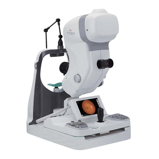
- Page 3 Accept our congratulations on your purchase of KOWA VX-20. KOWA VX-20 is a retinal camera which is capable of mydriatic and non-mydriatic photography. This manual provides a description of the operation procedures of KOWA VX-20 and important precautions to be observed during its use.
- Page 4 OFF the main power immediately and then unplug the instrument from the power outlet. Continued use of the instrument may cause the instrument to malfunction or cause a fire. Contact Kowa or your Kowa dealer for inspection immediately. When replacing the flash lamp and observation lamp, make sure the instrument is turned OFF and then unplugged from the power outlet.
- Page 5 Caution The power supply must be provided for the sole use of this instrument. Sharing a same power supply with other devices may cause malfunctioning. When operating the instrument, take good care so that the patient’s eye, nose or face does not come in contact with the instrument. When moving up or down the chin rest to adjust the height of the patient’s eyes, Obligatory carefully manipulate the instrument while checking the position of the patients’...
- Page 6 Caution for fingers location Keep your fingers off the location shown with the arrows in the illus- tration when operating this instrument. Otherwise, the fingers may be Caution pinched and injured. Instruct the patient not to place his or her fingers on the instrument. Caution for contact Take good care so that the patient’s eye, nose or face does not come in contact with the loca-...
- Page 7 Meanings of symbols Symbol for “Power ON”. Symbol for “Caution”. Symbol for “Power OFF”. Symbol for “Warning High-voltage”. Symbol for “Caution High-tempera- Symbol for “Type B applied part”. ture”.
- Page 8 3) Kowa is not liable for malfunctions and/or damages resulting from maintenance and/or repairs performed by the third party other than an agent authorized by Kowa. 4) Kowa is not liable for malfunctions and/or damages resulting from maintenance and/or repairs using parts other than repair parts specified by Kowa.
- Page 9 ● Combination of medical electrical equipment and non-medical electrical equipment IEC 60601-1-1 “Safety requirements for medical electrical systems” describes the components combination grouped into various clinical settings. The brief overview of IEC 60601-1-1 is shown below. Medically used room Feasible solution Non-medically Inside Outside...
- Page 10 IEC or ISO provisions applicable to such a non-medical electrical equipment. 5) Do not use any additional multi-tap or extension power cable other than those Kowa specified to this system. 6) Power supply to this system or “Multi-tap with Isolation Transformer” must be provided individually. (Do not route the power supply through other multi-tap to the system or “Multi-tap with Isolation Transformer”.)
- Page 11 5) The instrument must be cleaned prior to use so that there will be no problem when using it again. 6. In case of a problem or malfunction, stop the operation and contact Kowa or your Kowa dealer for repair.
- Page 12 Components and supplies Main unit Optical Component Power supply Accessories USB cable 1(A─mini-B type×2):1(2.3m) Objective lens cap holder: 1 Illumination lamp: 1 Instruction manual: 1 Blower:1 Dust cover:1 Setup manual: 1 Chin rest Chin rest paper Compact flash Hex wrenches: 3 Head bands: 2 Fuses:2 paper:1...
- Page 13 Optional accessories Internal fixation target: 1 Grips: 2 Forehead rest: 1 K9L-PE56 K9L-GR56 K9L-HR56 Exciter & Barrier filter set for FAF: 1 Bar code reader: 1(1.6m) Card reader: 1(1.2m) K9L-IF56K VK-CB2H VK-CB2G LAN cable(cross):1(5m) USB cable 2(A-B type):1(5m) K9L-SC56B K9L-SC56C...
-
Page 14: Table Of Contents
MENU Introduction ..................... I Operational considerations for safety ..................I Meanings of symbols ................V Operating precautions ................. VI Precautions: use of medical electrical system ........ VIII Operational considerations for hospital grade electrical instrument (safety and accident prevention) ............IX Components and supplies ..............X Main unit ..........................X Accessories ..........................X Optional accessories ......................XI... - Page 15 Mydriatic Fluorescein angiography procedures ............19 Viewer mode functions and procedures ..............23 Advanced operation ................30 Tilt and panning .......................30 Small pupil photography ..................31 LCD Monitoring ......................33 Switching fixation target ...................34 Additional adjustment of the flash intensity(+5 or more, 5 or less) ......37 Blue/Brown button ....................37 Customize button ....................37 Power saving function ....................38...
-
Page 17: System Description
System description 1.1 Indication for use The KOWA VX-20 is intended for taking picture of retinal images with mydriatic or without mydriatic. 1.2 System overview This instrument is a retinal camera, capable of capturing both non-mydriatic and mydriatic, has two photog- raphy field angles of 50º... -
Page 18: Name And Function Of Each Component
1 System description 1.4 Name and function of each component Main unit External fixation target It freely moves patient’s fixation. Optical viewfinder (eyepiece) This is an optical viewfinder (eye- piece) capable of using in mydri- atic color photography, Red Free photography, and Fluorescence angiography. - Page 19 1 System description Field angle selection button It is a button to switch the field angles between 50º/30º in mydri- atic, and between 45º/27º in nonmydriatic. Photography mode switching buttons FA button Observation light intensity con- It is a button to switch the photography mode to FA. trol knob RF/FAF button It is a knob to adjust the intensity of the...
- Page 20 1 System description Lamp cover W.D. switch It turns on/off the illuminating dots Air vent for detecting the alignment position of the retinal camera. It can be Wind generated by the internal used for mydriatic color photogra- cooling fan blows out. phy, Red Free photography, Fluo- rescence angiography, and auto- fluorescence photography (FAF).
- Page 21 1 System description I/O port Power supply unit Power switch Compact flash memory card insert slot It is a switch to turn on/off the power Accepts a compact flash memory card [supplied]. of this instrument. I: ON, : OFF Cable clamps Ejector button Used for holding cables to keep When pressed, the compact flash...
-
Page 22: Lcd Monitor Indications
1 System description 1.5 LCD monitor indications In this section, the information and buttons displayed on the LCD monitor are described. 1.5.1 Capture mode screen 1 Timer - Flash intensity compensation buttons By pressing the timer button in the Fluorescence angiogra- It appears when the flash intensity compensation knob on ─... - Page 23 1 System description When you press the “Fixation target selection button”, particular bottons appear shown below. VIEWER FIXATION VIEWER USER1 When you press the “PERIPHERAL button”, particular bottons below appear. USER2 STILL VIEW FIXTION CENTRAL USER3 RERI PHERAL DISC BLUE BROWN BACK NEXT MACULA...
-
Page 24: Preparation
2.2.1 Inserting a compact flash memory card Slowly insert the supplied compact flash memory card, Kowa logo facing up, in the compact flash memory card insert slot as far as it goes. -
Page 25: System Connection Configuration
• Stand-alone: Images taken by the instrument are acquired by the instrument itself as a stand-alone system. • VK connection: Images taken by the instrument are acquired directly by Kowa filing system. • Network connection: Images taken by the instrument are acquired by a computer via a network. -
Page 26: Turning On The Power
2 Preparation 2.3.2 VK connection In order to use this instrument in the VK connection setting, Kowa VK series (optional device) and the USB cable 1 are required. For information on the installation and use of the VK series, refer to the installation and the user manuals supplied with the VK series. -
Page 27: Retinal Camera Preparation
2 Preparation Notice ¿ Turning OFF the instrument without following the above procedures may result in a loss of data or damage to the instrument. With an exception of emergency situations, follow the above procedures to turn OFF the instrument. ¿... -
Page 28: Basic Operation
Basic operation 3.1 How to use the control lever The control lever is used to move the optical component of the retinal camera lengthwise or crosswise, and upward/downward. When roughly divided, there are three ways to use it: • Coarse motion: moves the optical component lengthwise or crosswise broadly. -
Page 29: Non-Mydriatic Photography/ Autofluorescence Photography Procedures
3 Basic usage 3.2 Non-mydriatic photography/ autofluorescence photography procedures This section describes the basic operation procedures for non-mydriatic and autofluorescence photography. The operation of buttons explained in the procedures is based on the factory default. If the settings have been changed, operate the buttons according to the modified settings. - Page 30 3 Basic usage 5 Select a fixation target. Press the “fixation target selection button” on the LCD monitor to select a fixation target and the position of the patient's eye fixation. 6 Compensate the diopter. As needed, press the “diopter compensation buttons” on the right side panel and use the diopter compensation lens.
- Page 31 3 Basic usage 9 Adjust the focus. Turn the “focusing knob” to adjust the focus. When you turn the focusing knob, the focus dots on the LCD monitor move left and right. Turn the focusing knob so that the upper and lower focus dots come to form a straight line.
-
Page 32: Mydriatic Color/ Red Free Photography Procedures
3 Basic usage 3.3 Mydriatic color/ Red Free photography procedures This section describes the basic operation procedures for mydriatic color photography and Red Free pho- tography. Notice ¿ In some cases, the use of mydriatics may aggravate patient's medical conditions or cause some pa- tients to go into shock. - Page 33 3 Basic usage 4 Adjust the flash intensity. The flash intensity is automatically set according to the photography mode. If it is necessary to adjust flash intensity, you may do so with the flash intensity compensation knob. 5 Select a field angle. Press the “field angle selection button”...
- Page 34 3 Basic usage 9 Guide the patient's fixation. Use the external fixation target to guide the patient's fixation position until the part you want to photograph becomes visible through the op- tical viewfinder (eyepiece). ¿ Position the external fixation target where the patient can fix the vi- sion with the eye not examined.
-
Page 35: Mydriatic Fluorescein Angiography Procedures
3 Basic usage 3.4 Mydriatic Fluorescein angiography procedures This section describes the basic operation procedures for mydriatic Fluorescein angiography. Notice ¿ In some cases, the use of mydriatics may aggravate patient's medical conditions or cause some pa- tients to go into shock. Be sure to read the instruction for use carefully before using mydriatics, and follow the instruction. - Page 36 3 Basic usage 4 Adjust the flash intensity. The flash intensity is automatically set according to the photography mode. If it is necessary to adjust flash intensity, you may do so with the flash intensity compensation knob. 5 Select a field angle. Press the “field angle selection button”...
- Page 37 3 Basic usage 9 Guide the patient's fixation. Use the external fixation target to guide the patient's visual fixation until the part you want to photograph becomes visible through the op- tical viewfinder (eyepiece). ¿ Position the external fixation target where the patient can fix the vi- sion with the eye not examined.
- Page 38 3 Basic usage \ Photograph the image. Press the “Shutter button” to activate the flash and photograph the image. When the connection configuration in “Stand-alone” or “Network con- nection”, images are displayed in the preview window immediately after they are photographed. ¿...
-
Page 39: Viewer Mode Functions And Procedures
3 Basic usage 3.5 Viewer mode functions and procedures This section describes various functions of the viewer mode. You may go to the viewer mode by pressing the “VIEWER button” on the LCD monitor while in the capture mode. You cannot take photograph in the viewer mode. Also, all buttons on the panel become disabled in this mode. - Page 40 ¿ Connect a card reader or bar code reader to the instrument before pressing the “Input ID button”. ¿ A card reader or bar code reader must be configured according to its usage environment. If you are to use a card reader or bar code reader, contact Kowa or your Kowa dealer in advance.
- Page 41 3 Basic usage Switching to another ID ─ ─ This function is enabled while the connection configuration is “Stand-alone.” You may switch from the current ID to an existing ID under which you want to save or view. Procedure 1 Press the “Input ID button” to go to the ID screen. 2 Select an ID from the ID list shown in the ** section of the screen.
- Page 42 3 Basic usage 3.5.3 Multiple image display This function is enabled while the connection configuration is “Stand-alone.” You may view the images saved under an ID, up to four images at a time. Four-image display ─ ─ Press the “MULT button” on the LCD monitor while on CAPTURE the single image display to show the four most cur- IN ID/LIST...
- Page 43 3 Basic usage Selected image display ─ ─ While on the four-image display, press any of the images to view. “Select ” is indicated on the corner of the selected images ( is a number of your selection). After making your selection, press the “MULT button” again to view only the selected images. Example: When 7, 3, 11, and 14 are selected in this order The selected images are displayed as shown above.
- Page 44 3 Basic usage 3.5.4 Deleting photographed images This function is enabled while the connection configuration is “Stand-alone.” You may delete images while viewing them. While on the single image display ─ ─ When you press the “TRASH button” while the image you want to delete is displayed, an alarm message appears.
- Page 45 3 Basic usage 3.5.5 Printing photographed images This function is enabled while the connection configuration is “Stand-alone.” You may print photographed images that are saved. CAPTURE IN ID/LIST REVIEW VIEW MULT PRINT No ID SETTING TRASH While on the single-image or multiple-image display, press the “PRINT button” to print the images that are shown.
-
Page 46: Advanced Operation
Advanced operation 4.1 Tilt and panning This instrument has the tilt and panning mechanism, which is used to photograph more surrounding field in mydriatic color photography and fluorescence angiography. 4.1.1 Tilt 1 Rotate the tilt lock knob to the left as you face directly to the tilt lock knob to release the lock. 2 Turning the tilting handle to the right (as you face directly to the tilting handle) allows you to tilt the op- tical component in an angle of depression. -
Page 47: Small Pupil Photography
4 Other functions 4.2 Small pupil photography This section describes how to photograph patients with a small pupil diameter. While this method allows you to photograph patients with a small pupil diameter, there are such disadvan- tages as smaller field angles or easier occurrence of a flare. Press the “S.P. - Page 48 4 Other functions The LCD monitor shows the approximate pupil diameter that may be photographed. The outer circle of the double circles shown in the illustrations below is the approximate pupil diameter that may be sufficiently photographed in the current diameter setting. The inner circle is the pupil diameter that may barely be photographed in the current diameter setting.
-
Page 49: Lcd Monitoring
4 Other functions 4.3 LCD Monitoring This section describes how to perform alignment on the LCD monitor without using the optical viewfinder (eyepiece) during mydriatic color photography, Red Free photography, fluorescence angiography, and mydri- atic monitoring in FAF. This function eliminates the need of diopter adjustment of the optical viewfinder (eyepiece). Also, this mode uses infrared rays instead of visible light to observe patients;... -
Page 50: Switching Fixation Target
4 Other functions 4.4 Switching fixation target This instrument automatically switches to an appropriate fixation target and the position of patient’s eye fixa- tion when the photography modes are changed. Please note that fixation targets are automatically switched according to the photography mode, not accord- ing to the state of the patient or the part required to be photographed. - Page 51 4 Other functions About “Peripheral” photography ─ ─ This section describes how to switch the light position of the fixation target and how to guide the patient's fixation when “Peripheral” photography is selected. Go to [Settings\Internal Fixation Target] to specify a photography sequence for a part to be photographed. When “Peripheral”...
- Page 52 4 Other functions About the internal fixation target (optional accessory) ─ ─ Use the internal fixation target (optional accessory) if you want to record the patient's fixation position in the photographed images. Attaching the internal fixation target 1) Remove the cover of the internal fixation target socket on the optical component. 2) Remove the protective tube of the internal fixation target.
-
Page 53: Additional Adjustment Of The Flash Intensity(+5 Or More, - 5 Or Less)
4 Other functions 4.5 Additional adjustment of the flash intensity(+5 or more, 5 or less) You may use this function to compensate the flash in- tensity beyond the compensation range allowed with the flash intensity compensation knob. When the flash intensity compensation knob is turned to +5, a "FLASH UP button”... -
Page 54: Power Saving Function
4 Other functions 4.8 Power saving function When the buttons on the operation panel and LCD monitor are not operated for a certain period of time (ap- proximately 10 minutes), the instrument goes into the power saving mode. During the power saving mode, the Power lamp is lit in green while all other lamps, such as LED lamps, ob- servation lamps, photography lamps, and LCD monitor backlight, are turned off. -
Page 55: Setting
Setting 5.1 Main 5.1.1 Monitor brightness In this tab, you may adjust the brightness of the LCD Main Capture Viewer Extension Maintenance monitor,from level 1 through 10 with an increment of LCD Bright Date Power Saving Sound System one. Adiust the moniter brightness. APPLY CANCEL 5.1.2 Date... - Page 56 ¿ When using the instrument in VK connection, use USB cable 1(A─mini-B type)(K9L-SC56A) to connect this instrument and a VK series model. ¿ When using the instrument in Network connection, make sure a network path is specified. If a net- work path is not specified, please contact Kowa or Kowa dealer representative.
-
Page 57: Capture
5 Setting 5.2 Capture 5.2.1 Flash intensity Increments of flash intensity: You may set 0.3EV or 0.5EV to calibrate the increment of increase/de- crease of the flash intensity compensation knob. Flash intensity indication: The flash intensity may be Main Capture Viewer Extension Maintenance displayed on the LCD monitor as the position of the Start up Image Quarity... -
Page 58: Viewer
5 Setting 5.2.3 Image quality/color This function is enabled while the connection configuration is in “Stand-alone” or “Network connection.” ¿ In “VK connection”, the image quality and color settings for the photographed images are configured in the VK series, which allows more detailed settings. To achieve images that are close to what you want, using the instrument in VK connection is recommended. -
Page 59: Advanced Functions
5 Setting 5.4 Advanced functions 5.4.1 Internal fixation target In this tab, you may configure the internal fixation target settings regarding “Peripheral”. You may set the lighting sequence of the fixation targets to be lit and whether the sequence for the right eye should be mirrored for the left eye. - Page 60 5 Setting Items to set Camera sensitivity : photography sensitivity of the camera. X1: Standard, X2: two fold, X4: four fold As the setting is changed from X1 to X4, photography with low flash intensity be- comes possible, but the image quality is compromised. Aperture size : the size of the camera aperture.
- Page 61 5 Setting 5.4.4 Blue/Brown You may select whether “Blue” or “Brown” is enabled Main Capture Viewer Extension Maintenance at the time of start-up. Int Fix Custom FA Filter Blue/Brown FAF Observe Set the initial setting (Blue or Brown). Brown Blue APPLY CANCEL 5.4.5 FAF observation...
-
Page 62: Maintenance
5 Setting 5.5 Maintenance 5.5.1 Making a backup copy of compact flash memory card You may make a backup copy of the data saved in Main Capture Viewer Extension Maintenance the compact flash memory card. BackUp Format Version Password Backup at CF card APPLY ※Connect the USB memory for backup. - Page 63 5 Setting 5.5.4 Setting a password You may set so that a password is required when making a backup copy or formatting a compact flash memory card. Select “Password” tab.5.5.4_1 Press “Set a password” button. 5.5.4_1 The window shown in 5.5.4_2 appears. Enter a password in the “New Password”...
-
Page 64: Troubleshooting
This section describes troubleshooting procedures to solve problems you may encounter. Look for the applicable symptom from those shown in the following list and apply the applicable remedy. When the described remedy did not eliminate the symptom or you encountered a symptom that is not listed, please contact Kowa or your Kowa dealer. - Page 65 6 Troubleshooting Abnormal performance of the instrument Symptom What to check · State of equipment Remedy The button different from the pressed button reacts during It is out of calibration. Calibration must be performed. LCD monitor operation. You cannot observe from the view- Non-mydriatic mode is enabled.
- Page 66 Is the pupil of the patient’s eye than the pupil diameter guideline, sufficiently dilated? the center of the images becomes dark. Images show black shadow spots at the same places. It is necessary to clean the inside of the camera. Contact Kowa or your Kowa dealer.
- Page 67 Connection of any uncertain peripheral Do not connect equipment which is not specified EPE01 equipment by Kowa. EPE02 Insufficient capacity of backup memory Replace the backup memory. EHW01 Failure of an optical unit (ring slit) Turn off the power and stop using.
-
Page 68: Maintenance And Inspection
Or, images may be out of fo- cus. When condensation occurs repeatedly, lenses may get moldy. When such a case has occurred to you, contact Kowa or your Kowa dealer. -
Page 69: Daily Inspection
7 Maintenance and inspection 7.2 Daily inspection Inspect this instrument in accordance with “KOWA VX-20 daily inspection table” below. KOWA VX-20 daily inspection table Inspection items Procedure Acceptability criteria Visually verify that plates and la- Plates and labels bels are readily readable and not Plates and labels are readable contaminated. -
Page 70: Daily Cleaning
6) If any soil is left out after cleaning according to the step 5), gently wipe off the soiled area with a cot- ton swab soaked with a little amount of water. If you have done this procedure, repeat the step 4). 7) Should you have any soil that cannot be removed by the steps above, contact Kowa or your Kowa dealer. -
Page 71: Replacement Of Consumables
7 Maintenance and inspection 7.3.2 Cleaning and disinfection of the parts where patients contact the instrument (the forehead base, the chin rest, and the grip (optional accessory)) Wipe the forehead rest (including K9L-HR56 (optional accessory)), head bands, the chin rest (in case not using the chin paper), and the grip (K9L-GR56 (optional accessory)) with rubbing alcohol as soon as a patient completes the examination. - Page 72 7 Maintenance and inspection 5) Hold the shade of the illumination lamp, pull the flat spring which fixes the lamp cover, and remove the lamp with the lamp socket from the lamp cover. 6) Hold the shade of the illumination lamp and pull it straight and slowly from the lamp socket 7) Attach a new illumination lamp to the lamp socket.
- Page 73 7 Maintenance and inspection 7.4.2 Replacement of the lamp for photography 1) Turn off the power switch and unplug the power plug from the electrical outlet. Wait for about 30 minutes and cool the lamp unit. 2) Remove the internal black lamp cover when replacing the illumina- tion lamp.
- Page 74 Obligatory 7.4.4 List of consumables Following is the list of consumables used on this instrument. Please contact Kowa or your Kowa dealer for purchase or any inquiry. It is recommended that you always stock the illumination lamp and the fuse for replacement.
-
Page 75: Regular Inspection
5. Switching operations of photography mode 6. Observation image using Standard Model Eye (OD) 7. Photography using Standard Model Eye (OD) 8. Photography light intensity 9. Electrical safety test Contact Kowa or your Kowa dealer for specific detail and cost of inspections. -
Page 76: Specifications
Specifications Mydriatic: 50º/30º Field angle Non- mydriatic: 45º/27º 39mm (between the patient’s eye and the front of the ob- Working distance jective lens) ─12D - +13D Diopter compensation range of patient’s eye ─ ─10D - ─32D +10D - +35D Focusing Split luminous bars coincidence (with ON/OFF function) Working distance adjustment Luminous dots indication (with ON/OFF function) -
Page 77: Technical Information
Technical information 9.1 Folder structure and data format of the compact flash memory card Image files (JPEG) and photography condition files (XML) are generated and saved in each of ID folders. File name [ID]_[YYMMDD]_[HHMMSS]_KOWA_[Photography type]_[Photographed eye]_[Timer elapsed time].Jpg [ID]_[YYMMDD]_[HHMMSS]_KOWA_ [Timer elapsed time].XML Patient's ID YYMMDD: Date of photograph taken... - Page 78 <nsCommon:Age></nsCommon:Age> <nsCommon:DOB></nsCommon:DOB> <nsCommon:NameJ1></nsCommon:NameJ1> <nsCommon:NameJ2></nsCommon:NameJ2> </nsCommon:Patient> <nsCommon:Operator> <nsCommon:No.></nsCommon:No.> <nsCommon:ID></nsCommon:ID> </nsCommon:Operator> <nsCommon:Parts> [2-digit maintenance code for Kowa] </nsCommon:Parts> </nsCommon:Common> <nsFUNDUS:Measure type=“FUNDUS”> <nsFUNDUS:FUNDUS> <nsFUNDUS:List No=“1”> <nsFUNDUS:ImageType> [Photography type] </nsFUNDUS:ImageType> <nsFUNDUS:AcquisitionDate> YYYY-MM-DD </nsFUNDUS:AcquisitionDate> <nsFUNDUS:AcquisitionTime> HH:MM:SS </nsFUNDUS:AcquisitionTime> <nsFUNDUS:Timer> [Timer elapsed time 00MMSSmmm] </nsFUNDUS:Timer> <nsFUNDUS:HorizontalFieldOfView unit=“deg”> [Field angle] </nsFUNDUS:HorizontalFieldOfView>...
-
Page 79: Number Of Photographs Taken Using The Supplied Memory Card
9 Technical information 9.2 Number of photographs taken using the supplied memory card The number of photographs you may take using the supplied 2-GB memory card depends on the photogra- phy mode as well as size and compression rate that are set according to 5.2.3. Image quality/color. The table below shows approximate number of photographs that may be taken with each setting. -
Page 80: Light Hazard (Iso 15004-2)
Light Hazard (ISO 15004-2) “Caution – The light emitted from this instrument is potentially hazardous. The longer the duration of exposure, the greater the risk of ocular damage. Exposure to light form this instrument when operated at maximum inten- sity will exceed the safety guideline after 1874 pulses for image capturing light, 206 min for illumination light, 30 min for working dots lights(visible), 7 hour for working dots light(IR), 43 hour for focus dots light(visible), 43 hour for focus dots light(IR), 7 hour for internal fixation light(red), 7 hour for internal fixation light(green), 440662 pulses for external fixation light(red), 536139 pulses for external fixation light(green).”... - Page 81 10 Light Hazard (ISO 15004-2)
- Page 82 10 Light Hazard (ISO 15004-2)
- Page 83 10 Light Hazard (ISO 15004-2)
-
Page 84: Electromagnetic Compatibility (Iec60601-1-2)
Electromagnetic compatibility (IEC60601-1-2) This instrument is a medical electrical instrument. Medical electrical instruments are requireed special attention to the electromagnetic compatibility (EMC). The following section describes the EMC and precautions regarding this instrument. When installing or using this instrument, read the description carefully and follow the directions described. - Page 85 Guidance and manufacturer’s declaration - electromagnetic emissions KOWA VX-20 is intended for use in the electromagnetic environment specified below. The customer or the user of KOWA VX-20 should assure that it is used in such an environment. Emissions test Compliance...
- Page 86 RF transmitters, an electromagnetic site survey should be considered. If the measured field strength in the location in which KOWA VX-20 is used exceeds the applicable RF compliance level above, KOWA VX-20 should be observed to verify normal operation. If abnormal performance is observed, additional measures may be necessary, such as re- configuring or relocating KOWA VX-20 b Over the frequency range 150kHz to 80MHz, field strengths should be less than 3 V/m.
Need help?
Do you have a question about the VX-20 and is the answer not in the manual?
Questions and answers