Table of Contents
Advertisement
Quick Links
Advertisement
Table of Contents

Summary of Contents for Konica Minolta SONIMAGE HS2
-
Page 3: Table Of Contents
Contents Introduction . . . . . . . . . . . . . . . . 7 Chapter 2 Before Examination . . . . . . . . . 69 Read First . - Page 4 Contents Chapter 4 Chapter 5 Diagnosis Mode . . . . . . . . . . . 123 Common Function in Ultrasound Images . . . . . . 181 4 .1 Basic Operation .
- Page 5 Contents Chapter 7 Chapter 9 Maintenance / Inspection . . . 233 MI/TI . . . . . . . . . . . . . . . . . . . . 271 7 .1 Maintenance Checks Before and After 9 .1...
-
Page 7: Introduction
Introduction... -
Page 8: Read First
If a user wishes to change image settings, the user can reconfigure the appropriate items . Konica Minolta shall in no event be liable for any defect that arises in connection with the system software being run on any computer other than the system . -
Page 9: Organization Of The Operation Manual
Read First Organization of the operation manual The operation manuals consist of the following volumes . z Operation Manual: Fundamentals It describes basic information on the system, such as setup for the system, part names, basic operations, common operations, the description of each mode, and maintenance . After completing initial setups, use it as a procedure manual for starting an examination and also as a measurement manual . -
Page 10: About Notational Convention Of The System
Read First About notational convention of the system Options, such as screen names / button names / on-screen choices, are surrounded by [ ] . Buttons are composed of the push buttons on the mini console and those selective buttons to be touched for the desired operation on the LCD monitor screen . -
Page 11: Trademarks And Copyrights
• This manual may not be reprinted in part or in whole without prior consent . • The contents of this manual are subject to change without notice . Copyright © 2020 Konica Minolta, Inc . All Rights Reserved . -
Page 12: Safety Precautions & Warnings
Safety Precautions & Warnings z There are DANGERs, WARNINGs, and CAU- Safety Alert Symbol TIONs at following pages . DANGER • "1 .1 Intended Use" • "8 .1 .1 Safety Precautions & Warnings for Trans- This is the "safety alert symbol" . This symbol alerts ducer"... -
Page 13: Notice Relating To Information Security
Safety Precautions & Warnings Notice relating to information security CALIFORNIA, USA ONLY This product contains a CR Lithium Battery which contains Perchlorate Material - special handling may WARNING apply . • Systems that have sustained cyber attacks, such as an attack via networks, wireless interception or www .dtsc .ca .gov/hazardouswaste/per- website browsing, or that are infected by computer chlorate... - Page 14 Safety Precautions & Warnings • Take precautions not to allow others to see the de- vice screen displaying sensitive patient information . Privacy protection display filters should not be used as such filters may adversely affect the appearance of displayed images •...
-
Page 15: Labels
Labels For safety use, labels that alert you to precautions for use are affixed on the system. Symbols on the warning labels ( , etc.) affixed on the system refer to precautions regarding safety. Information about labels is described in "Description of symbols" and the labels correspond to the numbers in the fol- lowing figure. -
Page 16: Main Unit Of The System
Labels Main unit of the system No . Label Description Affix on the back side of the main unit. **** ***** Model label **** ** 0197 ************** (01) **** ***** (21) Affix on the back side of the main unit. Windows label WARNING / CAUTION label Affix on the back side of the main unit. -
Page 17: Pole Cart2 (Option)
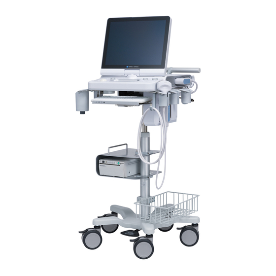
Labels Pole Cart2 (Option) No . Label Description Affix on the back side of the tray. This marking can be read from the bottom part of the Pole Cart2 . Label of origin CAUTION label Maximum total mass of the system System total weight label 45 kg (99 lbs) Basket maximum load label... -
Page 18: Power Extension Unit2 (Option)
Labels Power Extension Unit2 (Option) No . Label Description (10) Back side label (11) Rating label (12) CAUTION label (13) PSE label (Power Extension Unit2) CW kit (Option) No . Label Description Affix on the back side of the main unit. SONIMAGE HS1 CW Kit SONIMAGE HS1 CW (14) -
Page 19: Foot Switch (Triple) (Option)
Labels Foot Switch (Triple) (Option) No . Label Description SONIMAGE HS1 Foot Switch (Triple) SONIMAGE HS1 (16) Label of origin Battery (17) (20) (18) (19) No . Label Description (17) WARNING label (18) Label of origin (19) Label RoHS (20) Rating label... -
Page 20: Three-Port Probe Unit (Option)
Labels Three-port probe unit (Option) (22) (21) Printed on the surface No . Label Description SONIMAGE HS1 Three-Port Probe Unit SONIMAGE HS1 (21) Label of origin Reference Signal Unit (Option) (25) (23) (26) (24) No . Label Description (23) Part number (24) WARNING label... -
Page 21: Keyboard Kit (Option)
Labels No . Label Description (25) Rating label (26) Label of origin Keyboard kit (Option) (27) No . Label Description SONIMAGE HS1 Keyboard Kit SONIMAGE HS1 (27) Label of origin, WARNING label... -
Page 22: Vesa Attachment (Option)
Labels VESA attachment (Option) (28) No . Label Description SONIMAGE HS1 VESA Attachment SONIMAGE HS1 VESA (28) Label of origin Acoustic Standoff (Option) (29) No . Label Description (29) Label of origin... -
Page 23: Description Of Symbols
Labels Description of symbols Symbols written labels are described . No . Symbol Description Remarks (1), (5), (6), (11), (13), (14), (15), Serial No . (16), (18), (21), (23), (27), (28) (1), (5), (6), (11), (14), (15), (16), Date of Manufacture (18), (21), (23), (27), (28), (29) - Page 24 Labels No . Symbol Description Remarks Do not give an impact to the transducer, do not forcibly press it against hard items, and do not CAUTION: drop it . Do not forcibly twist or bend the cable . Do not give an impact to the transducer . Doing so may cause damage to the transducer Risk of transducer breakage .
- Page 25 Labels No . Symbol Description Remarks Marking requirements of the Battery Direc- (20) tive ECG Unit should be connected to the speci- Caution (24) fied ECG cable for the Reference Signal Unit. Catalog Number (25) Ejection Pushing this portion will eject the keyboard . (27) Withstand load The withstand load of the keyboard is 5 kg .
-
Page 26: Description Of Graphic Symbols
Labels Description of graphic symbols Location Graphic symbols Description Remarks Displays the start-up status . Refer to "Status indicator LED" of "1 .6 .3 Status indicator LED Mini Console" for details . Indication of the state of readiness of the batteries The power switch (standby switch) is Power switch located on the left side of the side panel of... - Page 27 Labels DANGER WARNING • To prevent the risk of injury or explosion, do not • Do not disassemble, repair, or modify the main unit . operate this system in a flammable or oxygen-en- Doing so may cause an electric shock . riched atmosphere .
- Page 28 • Do not connect peripheral units other than AC wet . Otherwise, the battery may overheat or the ter- adapter or printer authorized by Konica Minolta to minal sections may rust . the Power Extension Unit2 . Doing so may reduce •...
- Page 29 Labels CAUTION CAUTION • During an examination, do not touch the contact of • Ultrasound procedures should be used for valid the connector, the device connected to the connec- reasons, for the shortest period of time, and at the tor, and the patient at the same time . Touching them lowest mechanical/thermal index setting necessary at the same time may cause an electric shock .
- Page 30 Labels CAUTION CAUTION • Pay attention to the following points when moving • Note the following in regard to the patient ID entry . the system . – When performing a study of a new patient, make – When the system is installed on the Pole Cart2, sure to register and store the unique patient ID .
- Page 31 Labels CAUTION CAUTION Battery • Do not throw the battery or subject it to strong im- • Do not use this system in locations subject to in- pact . tense electric or magnetic fields (such as MRI or CT • The battery must be kept out of the hands of chil- scan equipment) to prevent the risk of interference dren .
- Page 32 Labels CAUTION CAUTION Barcode reader Mini console switch configuration • Do not damage acrylic window of the barcode read- • Do not press two or more switches on the mini er . Doing so may cause breakdown . console simultaneously . System malfunction may •...
- Page 33 Labels CAUTION CAUTION Measurements Study Data Review • Do not cancel FREEZE during measurement . Mea- • Do not display ultrasound images recorded or ed- surement data will be lost . ited by other devices on this system . (except library •...
- Page 34 Labels CAUTION CAUTION Wireless LAN Recording devices • Wireless LAN adapter of the system is for indoor • When recording diagnostic images, confirm that use only . Please remove the wireless LAN adapter the displayed patient ID and patient are matched . from the system in advance, if the system may be Recording diagnostic images with an incorrect pa- in the outdoor locations .
-
Page 35: Important Information
(6) Do not make changes or modifications to this system (including software). (7) Konica Minolta offers after-sales services at user's expense. Maintenance and inspection services to maintain the performance of this system are also available . Contact your service representative for more information . - Page 36 Important Information (17) Use the system under the specified environmental conditions. Otherwise, it may cause failure of the system . (18) The following instructions must be observed in order to prevent this system from being infected with malware (malicious software, such as a computer virus or worm that harms computers) . If the system is infected with malware, the data stored in the system may be lost, tampered with, or leaked;...
- Page 37 Important Information (26) Observe the instructions below to prevent damage of the user’s network environment (e .g ., unstable operation and security hole) . • Users should configure secure environment, manage risks and follow the instructions for use when using net- work/external storage media/printer .
- Page 38 Important Information (30) This system is intended for use in the following environment . • Hospital facilities • Indoor examination room that is managed equivalent to hospital facilities • Inspection rooms • Wards • Emergency rooms (31) Do not use this system in the following environment . •...
-
Page 39: Disclaimer
(8) Konica Minolta shall not be liable for any loss or damage caused by fire, earthquake, flood, lightning or any other act of GOD . (9) Konica Minolta shall not be liable for any loss or damage resulting from any use of the system other than for its intended purposes . -
Page 40: Software License
The software used for this system includes software owned by Konica Minolta and licensed to Konica Minolta by a Licensor . Konica Minolta sells the system on which this software is installed by licensing a user of the system to use the software . -
Page 41: Support
Support For all product inquiries, contact your service representative . -
Page 43: Product Overview
Chapter Product Overview... -
Page 44: Intended Use
1 .1 Intended Use The Ultrasound System SONIMAGE HS2 is a portable IMPORTANT •••••••••••••••••••••••••••••••••• • •• ultrasound system for general purposes . • The system should not be used by persons other This system provides ultrasound images in all its than fully qualified and certified medical personnel. -
Page 45: Features
1 .2 Features z Clear B image The adoption of the full digital transmission / reception circuit allows high-definition beams, helping achieve high- quality / high-sensitivity images . In particular, the device structures and constituent materials of linear transducers have been improved to provide high quality images . -
Page 46: Operating Principles
1 .3 Operating Principles This system transmits ultrasound signals into the human body from an ultrasound transducer and receives the re- flected echoes from the human body using the same transducer. It then processes the received signals to display them as images on a display screen (LCD monitor) and to generate Doppler sound from a speaker . Gating signals are sent from the scan control circuit through the transmission delay circuit and are input to the trans- mission circuit . -
Page 47: Specifications
1 .4 Specifications Item Description Ambient temperature :10 °C to 35 °C Relative humidity :30 % to 80 % (no condensation) Operation environment Atmospheric pressure :700 hPa to 1060 hPa Altitude :3000 m or less Ambient temperature: -20 °C to 60 °C (30 days) -20 °C to 40 °C (90 days) -20 °C to 20 °C (1 year) (The following applies when the main unit is equipped with the Clear Ball (option) .):... -
Page 48: Patient Environment
1 .5 Patient Environment This system is designed to be used in the environment specified in the figure below. However, the external monitor should be used on the outside of patient environment . Note that, when using the ex- ternal monitor, you have to observe the following items . •... -
Page 49: System Configuration And Part Name
1 .6 System Configuration and Part Name 1 .6 .1 Standard Configuration No . Item Quantity (pieces) Main unit of the system (The LCD monitor is included .) AC adapter (100 V to 240 V supported) Model: ATM200T-P240 (Manufacturer: Adapter Technology) Fuse (A user is not able to replace the fuse .) Fuse size of F1 and F2 : φ... -
Page 50: Part Name
1.6 System Configuration and Part Name 1 .6 .2 Part Name z Front (when used) LCD monitor Touch panel-type LCD Air vent Mini console Transducer connector lock Transducer connector (without a transducer mounted) Handle • You can hold the handle for carrying the system . z Rear (when used) Power supply cord Battery... - Page 51 1.6 System Configuration and Part Name • • • • • • • • • • • • • • • • • • • • • • • • • • • • • • • • • • • • • • • • • • • • • • • • • • • • • • • • • • • • • • • • • • • • • • • • • • • • • • • • • • • • • • • • • • • • • • • • • • • • • HINT To open the monitor 1 Press the LCD latch, and raise the monitor .
-
Page 52: Mini Console
1.6 System Configuration and Part Name 1 .6 .3 Mini Console CAUTION • • • • • • • • • • • • • • • • • • • • • • • • • • • • • • • • • • • • • • • • • • • • • • • • • • • • • • • • • • • • • • • • • • • • • • • • • • • • • • • • • • • • • • • • • • • • • • • • • • • • • •... - Page 53 1.6 System Configuration and Part Name z Main functions of mini console keys Item Functions EXIT button Ends a currently-used application or the like . SET button Accepts the selection . When operating with the trackball, move the cursor to the desired position and press the SET button to accept the selection .
- Page 54 1.6 System Configuration and Part Name z Default settings for mini console keys The roles of the button to which the SET * function is assigned and the FREEZE button do not change depending on the image mode or functions being run when the buttons are pressed . Other key defaults are listed below . CFM / PDI / 2D-TDI / PW / CW / B-mode...
- Page 55 1.6 System Configuration and Part Name Body mark Compare view Measure function Text function Other function function EXIT [EXIT] button F2 * Operation item switching Rotate function * button [Undo Measure] / [Auto Annotation] [Transducer angle F2 Rotate 1 [Redo Measure] [Rotate Arrow] rotation] F2 Rotate 2...
- Page 56 1.6 System Configuration and Part Name z Software trackball You can use the system simply by using on-screen touch control . Press the [Menu] button > the [Other] tab > the [Trackball] button to display the software trackball . Another way to display the software trackball is to press the [Measure] button . The software trackball appears at the lower left corner of the screen .
-
Page 57: Side Panel / Rear Panel
1.6 System Configuration and Part Name 1 .6 .4 Side Panel / Rear Panel The power switch and various connectors, etc . are located on the side / rear panels . Side panel The peripheral devices can be connected to each side panel . z Left side (when used) (2) (3) No . - Page 58 1.6 System Configuration and Part Name Rear panel The peripheral devices can be connected to the rear panel . No . Name Functions Power connector AC adapter cable inlet Security lock Security wire installation hole DVI-D terminal Output terminal for external imaging system Ethernet connector Output terminal for network transfer of digital images USB2 .0 port...
-
Page 59: Monitor
. Status indicator icon KONICA MINOLTA Logo IMPORTANT • • • • • • • • • • • • • • • • • • • • • • • • • • • • • • • • • • • • • • • • • • • • • • • • • • • • • • • • • • • • • • • • • • • • • • • • • • • • • • • • • • • • • • • • • • • • • • • • • • • • •... - Page 60 1.6 System Configuration and Part Name z Touch panel function You can press (touch) the desired button or option on the monitor to select it, or move (drag) a thumbnail to the de- sired location using your finger. • Available buttons and functions differ depending on the mode or application being used. •...
- Page 61 1.6 System Configuration and Part Name No . Item Timing of display Functions Always when you already Network connection Displays when connected to a network via wired LAN connec- have the network set up status tion . Not connected: Connection established: Network error: Refer to "Network Screen"...
- Page 62 1.6 System Configuration and Part Name Information of service representative z How to show Touch the KONICA MINOLTA logo area, or click it with a free cursor, to display the information of service representa- tive in a pop-up window . • [System Name] •...
-
Page 63: Compatible Peripheral Devices
Items complying with IEEE 802 .11n, IEEE 802 .11a, IEEE 802 .11g or IEEE 802 .11b . The compatible standard differs depending on the wireless LAN adapter. Only the items authorized by Konica Minolta . To use the wireless LAN connection, an optional "Wireless LAN License" is required . - Page 64 1.6 System Configuration and Part Name SD memory card Recommended SD memory cards used in this system are listed below . To purchase the SD memory card, contact your service representative . SDHC memory card Class10 PFS0032U series (from TOSHIBA) PFS0032U-1DCK (32 GB), PFS016U-1DCK (16 GB), PFS008U-1DCK (8 GB) SDHC memory card Class10 specs SD-WA series (from Panasonic) SDHC memory card Class4 specs SD-LB series (from Panasonic)
-
Page 65: Biopsy Brackets
1.6 System Configuration and Part Name 1 .6 .7 Connectable Transducers and Biopsy Brackets A transducer is a device designed for transmitting / receiving ultrasound . The system supports the following transducers and biopsy brackets, which are all optional . The transducer that can be used with the system varies depending on the unit . -
Page 66: List Of Optional Items
It allows black-and-white printing on VCP paper . Black-and-white printer * (13) Only the items authorized by Konica Minolta . For details, refer to the operation manual of the USB printer . The Clear Ball can be illuminated only after it is replaced with the trackball... - Page 67 1.6 System Configuration and Part Name z License No . Name Notes DICOM Storage License Refer to "DICOM Screen" of the "Operation Manual: Applications" . Auto IMT License Refer to "Auto IMT" of the "Operation Manual: Applications" . Simple Needle Visualization License Refer to "8 .2 .6 Simple Needle Visualization"...
-
Page 69: Before Examination
Chapter Before Examination... -
Page 70: Installation
2 .1 Installation There are three types of usage of the system . 2 .1 .1 Moving the System • Desktop Put the system on a table . • Pole Cart2 The system can be moved independently within the Attach the system to the Pole Cart2 (optional) . hospital setting . - Page 71 2 .1 Installation ••••• •••••••••••••••••••••••••••••••• CAUTION • Do not step on or trip over the power supply cord of the system . Doing so may cause injury or damage to the system . • Pay attention to the following points when carrying this system .
-
Page 72: Connecting The Transducer
2 .1 Installation 2 .1 .2 Connecting the Transducer Only a single transducer can be directly attached to the transducer connector of the system . Up to three transducers can be attached if you use an optional Three-Port Probe Unit . Information from the transducer attached to the port is displayed on the ultrasound image . - Page 73 2 .1 Installation Raise the lock lever to secure the transducer . Transducer connector lock Turn ON the system . • The attached transducer is recognized by the system so that the frequency display and icon will be changed accordingly . z How to remove Turn OFF the system .
-
Page 74: Three-Port Probe Unit
2 .1 Installation 2 .1 .3 Three-Port Probe Unit There are three transducer connectors, which are selectable through the operation of the mini console of the system or the touch panel without removing the transducer . Three-Port Probe Unit IMPORTANT •... -
Page 75: Battery Capacity
IMPORTANT • •• ••• •• •• •• ••• •• •• •• ••• •• •• •• •• • • • • • • An AC adapter authorized by Konica Minolta must be used . • Make sure to fully insert the AC adapter connec- tor . - Page 76 2 .2 Power Supply Cord Connection and Battery Capacity When the Power Extension Unit2 is not used When the Power Extension Unit2 is used Clamp AC adapter cable Clamp MagicBand Cable hook Φ130 mm Wind the cable twice with a circle of Φ130 mm, fix it with two Power Extension Unit2 MagicBands, place...
-
Page 77: Battery Capacity
2 .2 Power Supply Cord Connection and Battery Capacity z How to remove 2 .2 .3 Battery Capacity Go through the steps below to remove the AC adapter . Disconnect the mains plug from the wall When using the system without connecting the power mounted AC socket outlet . - Page 78 2 .2 Power Supply Cord Connection and Battery Capacity z Battery status indicator • Unknown The system monitors the status of the battery’s re- Battery's remaining Status indicator icon maining capacity / AC adapter connection, and informs capacity you of changes, if any, in each status by varying the on-screen status indicator icon and the status indicator –...
-
Page 79: Power On/Off
2 .3 Power ON/OFF 2 .3 .1 Turn ON the Power 2 .3 .2 Turn OFF the Power Open the LCD monitor and adjust the an- Press the power switch when the power is gle of the monitor . ON . •... -
Page 80: Standby
2 .3 Power ON/OFF z Shutdown function 2 .3 .3 Standby Pressing the power switch will display the message asking you to select the desired shutdown type . z Power switch > Shutdown confirmation List of shutdown confirmation message buttons message >... -
Page 81: Security Functions
2 .3 Power ON/OFF 2 .3 .4 Security Functions The system is equipped with the following security functions: Account management, Login / Logout, Security log, and Screen lock . z Login function The [Login] screen appears during the start-up of the system or after logging out of the system . The login function is enabled when the [Login required] setting for the security functions is set to ON . - Page 82 2 .3 Power ON/OFF Press the [OK] button . • Performs a user authentication operation to put the system into a login state . • Ultrasound examinations become available once logged in . Item Functions [Name] Enter your user account name . [Password] Enter your password .
-
Page 83: External Device Link
2 .4 External Device Link 2 .4 .1 ImagePilot Link This system cooperates with the external link device ImagePilot via LAN to improve the operability of patient informa- tion registration . ImagePilot refers to a diagnostic imaging work station that allows total control of various procedures, such as regis- tration of patient/imaging information and confirmation of images, and it helps provide a more comfortable and effec- tive diagnostic environment . -
Page 85: Starting Examination
Chapter Starting Examination... -
Page 86: Study Screen
3 .1 Study Screen When the power is turned ON and the system starts up, the study screen is displayed on the LCD monitor . 3 .1 .1 Layout of the Study Screen The monitor displays ultrasound images, the operation menu or other various information . The screen is divided into 8 areas as shown below . - Page 87 3 .1 Study Screen No . Area Functions The [Study] button and the status indicator icon are located here . Status area • The [Study] button function differs depending on the settings. For details, refer to "[Study Button] customize" in the "Operation Manual: Applications" . Operation button area Thumbnails and operation buttons are located .
-
Page 88: Displaying Common Data
3 .1 Study Screen 3 .1 .2 Displaying Common Data In the image display area, various data of image-related information such as parameters are displayed . This section describes the common data displays in each mode . • Numbers on the image are a numerical display sample . Gray bar / Color bar area Parameter display area B-image scale... - Page 89 3 .1 Study Screen Gray bar / Color bar area Displays the blood flow velocity and scale bar in each mode. No . Item Functions Gray Scale Bar Displays the B-image scale bar . Numerical display Displays the maximum velocity in Color Flow-mode / 2D-TDI-mode . Displays the scale bar in Color Flow-mode / 2D-TDI-mode / Power Doppler-mode / Color Scale Bar SCF-mode / Elastography-mode .
- Page 90 3 .1 Study Screen z M-mode image Depth scale Time marker Sweep marker Setting item OFF * Setting item ON * L/R display Other than L/R display Latest M-image position Position in 0 .5-second Right Left Not displayed . (only in live state) and 1-cm increments *: Go to [Setup] screen >...
- Page 91 3 .1 Study Screen Parameter display area Displays mode-specific parameters. • The following figure is an example of the display format and numerical values used in other modes than dual mode . (10) (11) (12) (13) (14) (15) Reference • • • • • • • • • • • • • • • • • • • • • • • • • • • • • • • • • • • • • • • • • • • • • • • • • • • • • • • • • • • • • • • • • • • • • • • • • • • • • • • • • • • • • • • • • • • • • • • • • • • • • •...
- Page 92 3 .1 Study Screen No . Data name Functions Frame Rate Displays the frame rate . Always displays the Tx level . Tx Level • The value is in "%" . THI On/Off Displays On / Off of THI. Displays the type of transducer frequency in B-mode or M-mode . Frequency Type (B/M) •...
-
Page 93: Examination Flow
3 .2 Examination Flow This section describes the general flow of an examination using the system. For information about each screen and basic functions, see the item to be described later in this chapter . Refer to the "Operation Manual: Applications" for details on such procedures as exam type-specific measurement procedures. Change to the [Patient] screen . - Page 94 3 .2 Examination Flow Registered patient • Patient information can be called up by searching using a patient ID or patient name . Select the desired patient and go to step 3 . Reference • • • • • • • • • • • • • • • • • • • • • • • • • • • • • • • • • • • • • • • • • • • • • • • • • • • • • • • • • • • • • • • • • • • • • • • • • • • • • • • • • • • • • • • • • • • • • • • • • • • • • •...
- Page 95 3 .2 Examination Flow Select and store an image using the Cine function . • When the Cine bar in the lower right corner of the image display area has been displayed, you can play back a desired frame by moving the trackball right and left . When you have selected your desired image, press the [Store] button in the lower right corner of the study screen .
-
Page 96: Registering Patient Information
3 .3 Registering Patient Information Patient information is registered on the [Patient] screen . The [Patient] screen includes the [Register] screen and the [Archive] screen . Press the desired button to change the display and enter information required for an examination . When you have started an examination without registering patient information, a Patient ID will be automatically is- sued if you have stored a still image or clip on the study screen . - Page 97 3 .3 Registering Patient Information z Patient information operation area Item Functions [Basic] tab Changes to the [Basic] screen . [Advance] tab Changes to the [Advance] screen corresponding to an examination . The selected exam type will be subject to [Exam] at the start of the examination . •...
-
Page 98: Keyboard
3 .3 Registering Patient Information 3 .3 .2 Entering Letters Using the Software Keyboard Use the software keyboard for entering letters . Touching a letter type field will display the keyboard, and touching a numerical type field, such as the one for age, will display the numerical keypad . -
Page 99: Entering Patient Information
3 .3 Registering Patient Information 3 .3 .3 Entering Patient Information The patient information entry area includes the [Basic] screen and the [Advance] screen and touching a tab will allow you to change and operate the screen . You can enter, search or change patient information . Patient information entry area [Basic] •... - Page 100 3 .3 Registering Patient Information Item Functions Enter an operator . • The entered operators can be selected from the pull-down menu . [Operator] * • The 20 latest used names are displayed in the pull-down menu . • If the number of registered names exceeds 20, the oldest name will be deleted . •...
- Page 101 3 .3 Registering Patient Information z To manually enter ID Touch the [ID] field. • The software keyboard appears . HINT • • • • • • • • • • • • • • • • • • • • • • • • • • • • • • • • • • • • • • • • • • • • • • • • • • • • • • • • • • • • • • • • • • • • • • • • • • • • • • • • • • • • • • • • • • • • • • • • • • • • • •...
- Page 102 3 .3 Registering Patient Information Item Functions Select a physician from the physician list . • [Setup] screen > [System Settings] screen > [Patient] tab > [Operator & Physician List] button > [Physician] where physician names are displayed in list form . [Physician] * •...
-
Page 103: Exam Type Selection
3 .4 Exam Type Selection z Exam type and preset Exam types are provided with preset items, each of which is related to any of the exam types . Exam items can be enabled/disabled on the [Setup] screen, and only presets or user presets related to effective exam types are selectable . -
Page 104: Examination
3 .4 Exam Type Selection 3 .4 .1 Select Preset / User Preset to Start Examination After registering, or calling up from the retrieval patient information on the [Patient] screen, select an exam from the pull-down menu . • By touching a desired exam type, the relevant preset items for the exam type will be displayed in list form . From the list you can select a desired preset item . -
Page 105: Patient Search
3 .5 Patient Search For a registered patient, the patient information can be called up using the patient search function . Select a desired patient from the search results and press the [Start Study] button to start an examination . Although both the [Register] and [Archive] screens of the [Patient] screen display the search function, it is necessary to select between the two screens according to the specified search item. -
Page 106: Searching
3 .5 Patient Search 3 .5 .2 Searching Touch the patient information area at the top of the study screen to change the screen to the [Patient] screen . Enter a search word in both fields of [ID] and [NAME], or in either of them. The list of search results is displayed in both a pull-down menu and the [Patient List] area . - Page 107 3 .5 Patient Search Touch a target patient to select from the list . • The past data of the patient is displayed on the study list and the latest study has been selected . (As indicated by the study list shown in the figure below) •...
- Page 108 3 .5 Patient Search z [Patient List] area Item Functions Select a study date range to search . [Study Date] • You can refine your search by study date. Select the number of records to be displayed for search operation . [Number] •...
-
Page 109: Edit And Delete Patient Information
3 .6 Edit and Delete Patient Information The [Archive] screen allows you to edit / delete the patient and study information of a patient for whom an examination is finished. HINT • • • • • • • • • • • • • • • • • • • • • • • • • • • • • • • • • • • • • • • • • • • • • • • • • • • • • • • • • • • • • • • • • • • • • • • • • • • • • • • • • • • • • • • • • • • • • • • • • • • • • •... -
Page 110: Study Data
3 .6 Edit and Delete Patient Information 3 .6 .2 Deleting Patient Information and Study Data IMPORTANT • • • • • • • • • • • • • • • • • • • • • • • • • • • • • • • • • • • • • • • • • • • • • • • • • • • • • • • • • • • • • • • • • • • • • • • • • • • • • • • • • • • • • • • • • • • • • • • • • • • • • •... -
Page 111: Data Backup
3 .7 Data Backup For securing the free space of the Internal storage capacity, it is recommended to store the settings for the system and the patient / study data regularly in external storage media . Each item of data can be backed up on the [Backup / Restore] screen . IMPORTANT •... - Page 112 3 .7 Data Backup HINT • • • • • • • • • • • • • • • • • • • • • • • • • • • • • • • • • • • • • • • • • • • • • • • • • • • • • • • • • • • • • • • • • • • • • • • • • • • • • • • • • • • • • • • • • • • • • • • • • • • • • •...
- Page 113 3 .7 Data Backup z Backing up the settings for the system Press the [Backup Setup] button on the [Backup / Restore] screen . • The screen changes to the [Backup Setup] screen . Step 3 Step 2 Step 4 Select a backup destination from the [Device] pull-down menu .
- Page 114 3 .7 Data Backup z Backing up patient / study data Press the [Backup Study Data] button on the [Backup / Restore] screen . • The screen changes to the [Backup Study Data] screen . Step 3 Step 2 Step 4 Select a backup destination from the [Device] pull-down menu .
- Page 115 3 .7 Data Backup Restore This function is used to repair or restore all or part of data . There are two Restore methods . • Restoring the settings for the system • Restoring patient / study data z Restoring the settings for the system Press the [Restore Setup] button on the [Backup / Restore] screen .
- Page 116 3 .7 Data Backup z Restoring patient / study data Press the [Restore Study Data] button on the [Backup / Restore] screen . • The screen changes to the [Restore Study Data] screen . Restore data using the same procedure as that of "Restoring the settings for the system" (above) .
- Page 117 3 .7 Data Backup Import This function is used to input the patient data in a CSV file. Press the [Patient Information CSV Import] button on the [Backup / Restore] screen . • The screen changes to the [Patient Information CSV Import] screen . Step 2 Step 3 Select an input destination from the [Device] pull-down menu .
- Page 118 3 .7 Data Backup z Converting the patient data A CSV file that can be input into the system is only the format created using the function of exporting patient informa- tion to CSV . To input a CSV file of patient information, which was created with other device, convert the file into the format that can be input to the system, using the conversion tool .
- Page 119 3 .7 Data Backup Item Functions Specify a delimiter for patient name in the input file. [None]: A patient name is not divided but converted as a family name . [Name Defines] [Separator] [[ ] (space)]: A patient name is divided into five parts with one-byte spaces. (default) [^]: A patient name is divided into five parts with the delimiter "^".
-
Page 120: Resuming Examination
3 .8 Resuming Examination As for study data of an examination within 24 hours after the examination ends, you can resume the examination . Use any of the following procedures to display study data of an examination within 24 hours on the [Archive] screen . •... -
Page 121: Emergency Examination
3 .9 Emergency Examination The Auto ID function allows you to start an emergency examination on the [Patient] screen or the study screen . An examination can be resumed only within 24 hours . You can edit patient information all the time, and after re- registering information on a patient in the same format as commonly used for patients in general, you can browse the information on the patient, or call up the information to examine the patient as a registered patient . -
Page 123: Diagnosis Mode
Chapter Diagnosis Mode... -
Page 124: Basic Operation
4 .1 Basic Operation The system is directly operable on the touch panel . The on-screen menus are used to display and operate functions that are not located on the mini console as neces- sary . Some button functions allow a pop-up window to appear, or help you to display hidden buttons by pressing in the button area and switching the page . -
Page 125: Menu Pop-Up Window
4 .1 Basic Operation 4 .1 .1 Menu Pop-up Window Pressing the [Menu] button will display the menu pop-up window on the screen . Equipped with a tabbed display, the pop-up menu consists of the image parameter change tab for the currently selected mode and the [Other] tab used for selection of functions . -
Page 126: Operation Buttons
4 .1 Basic Operation 4 .1 .2 Operation Buttons In the operation button area, various function buttons are located and each button serves as a key to switch ON/OFF . Up to four buttons can be located . If all buttons cannot be displayed in one page, press to switch the display . - Page 127 4 .1 Basic Operation Button Functions Executes the store still image or clip function . You can assign functions according to the [Store] settings . [BW Print] Executes the BW print function . [Still Store] Executes the still image store function . [Clip Store] Executes the clip store function .
- Page 128 4 .1 Basic Operation Button Functions Every time you press the button during an exam, you can change the port that is con- nected to the transducer (Port1→ Port2→ Port3). [Transducer] Ports to which no transducer is attached are skipped, and if only one transducer is con- nected, the button does not operate even if it is pressed .
-
Page 129: Orientation
4 .1 Basic Operation 4 .1 .3 Display of Ultrasound Image and Orientation The scan mark indicating the ultrasound scanning direction is displayed on the screen . Scanning direction mark Refer to "8 .1 .3 Transducer Part Names" . Scan starting point Scan mark Indicates that a scan is starting from the right side of the screen . -
Page 130: Changing Exam Type Or Preset During
4 .2 Changing Exam Type or Preset during Examination 4 .2 .1 Changing Exam Type Using the Shortcut Window Touch the transducer mark icon at the bottom right of the study screen . • The exam type select shortcut window appears . Up to twelve exam type shortcuts are located in the shortcut window . - Page 131 4 .2 Changing Exam Type or Preset during Examination z [Preset / Transducer Select] screen If you want to select an exam type or preset not shown in the dialog box, go to the [Preset / Transducer Select] screen . Touch the preset icon in the exam type select shortcut window .
-
Page 132: Registering User Preset
4 .2 Changing Exam Type or Preset during Examination 4 .2 .2 Registering User Preset The image parameter changed during an examination can be registered as a user preset . This is useful for reproducing the settings of image parameters in a different examination. Press the [Menu] button >... - Page 133 4 .2 Changing Exam Type or Preset during Examination Touch the [User Preset Name] input field. • A software keyboard appears . Type in letters using the keyboard for registering a user preset name . Press the [Save] button to return to the study screen . HINT •...
-
Page 134: Diagnosis Mode Types
4 .3 Diagnosis Mode Types With the system you can use three types of diagnosis modes: basic scanning, mixed and multi-image . Select the desired button from the mode button area to change the diagnosis mode . Mode button area The currently selected scanning mode is lit, showing that it is in active use . - Page 135 4 .3 Diagnosis Mode Types Diagnosis mode types available for the system are as follows . For details, see the section on each mode . Mode Type B-mode M-mode Color Flow-mode Power Doppler-mode 2D-TDI-mode Basic scanning mode SCF-mode PW Doppler-mode PW-TDI-mode CW Doppler-mode Elastography-mode...
-
Page 136: Basic Scanning Mode
4 .4 Basic Scanning Mode According to the intended examination, a scanning mode is selected from the mode button area . 4 .4 .1 B-mode B-mode is a basic scanning mode of the diagnostic ultrasound system, which displays a brightness-modulated cross- sectional image of the organ being imaged . - Page 137 4 .4 Basic Scanning Mode B-mode parameter list Item Functions TX level settings [Tx Level] • Displayed in all modes . Focal position setting for B-mode [Focus Position] • Shared with M-mode . • The actual focal position depends on the transducer used . Frequency setting for B-mode •...
- Page 138 4 .4 Basic Scanning Mode Item Functions [THI] THI settings for B- and M-mode Sets whether to display parameters during dual mode (displaying images side-by-side) . • When it is set to [Off] or [Trans.], the ultrasound image is also displayed even in the parameter [Param .
- Page 139 4 .4 Basic Scanning Mode This is a parameter to determine the receive gain (offset) in relationship to the depth direction. The receive gain relative to the depth direction of an image is adjusted for individual transducers and is set to a stan- dard value so that normally you can acquire a good view of the image even if all TGCs are positioned to the center .
-
Page 140: M-Mode
4 .4 Basic Scanning Mode 4 .4 .2 M-mode In M-mode the B image area is specified using the M cursor, which displays a change over time. This mode is suitable for observation of active organs such as heart valves . It also allows a B-mode image to be dis- played, and an observation area to be displayed or sized in the B image . - Page 141 4 .4 Basic Scanning Mode M-mode parameter list Item Functions Sets the transmission voltage . [Tx Level] • Displayed in all modes . [Sweep Speed] Sweep speed setting for M-mode [M Layout] Display layout setting for M-mode Gain offset setting for M-mode [M Gain] •...
- Page 142 4 .4 Basic Scanning Mode When [Ana-M] is set to [On], the freely movable Ana-M cursor and the rotation center cursor appear . Ana-M cursor Rotation center cursor <Anatomical M image> • The Ana-M cursor can be rotated centered on the rotation center cursor by the Angle operation (the item in the M- mode menu or F2 Rotate) .
- Page 143 4 .4 Basic Scanning Mode z To exit Set [Ana-M] to [Off]. • When an operation to quit M-mode is performed, Anatomical M-mode is forced to quit . • • • • • • • • • • • • • • • • • • • • • • • • • • • • • • • • • • • • • • • • • • • • • • • • • • • • • • • • • • • • • • • • • • • • • • • • • • • • • • • • • • • • • • • • • • • • • • • • • • • • • HINT •...
-
Page 144: Color Flow-Mode
4 .4 Basic Scanning Mode 4 .4 .3 Color Flow-mode In Color Flow-mode, color blood flow patterns are displayed within the Region of Interest (ROI) in a B image. ROI is called "C ROI" in Color Flow-, Power Doppler-, 2D-TDI- and SCF-mode . This mode is suitable for the study of the character, average velocity and direction of blood flow. - Page 145 4 .4 Basic Scanning Mode Color Flow-mode parameter list Item Functions Sets the transmission voltage . [Tx Level] • Displayed in all modes . Velocity setting for Color Flow-mode [C Scale] • The parameter range depends on the transducer used . Steer angle setting for Color Flow-mode [C Steer] •...
-
Page 146: Power Doppler-Mode
4 .4 Basic Scanning Mode 4 .4 .4 Power Doppler-mode In Power Doppler-mode, the intensity of blood-flow color is displayed in the ROI in a B image. This mode is suitable for the study of the character and volume of blood flow. It also allows a C ROI to be displayed or sized in the B image . - Page 147 4 .4 Basic Scanning Mode Power Doppler-mode parameter list Item Functions Sets the transmission voltage . [Tx Level] • Displayed in all modes . [C Scale] Velocity setting for Power Doppler-mode Steer angle setting for Power Doppler-mode [C Steer] • Enabled when a linear transducer has been connected to the system . [C Gain] Gain setting for Power Doppler-mode [C Filter]...
-
Page 148: Tdi-Mode
4 .4 Basic Scanning Mode 4 .4 .5 2D-TDI-mode In 2D-TDI-mode, information on tissue movements is displayed within the Region of Interest (ROI) in a B image . This mode is suitable for studying movements of the heart wall . This mode allows you to display a C ROI and adjust the size within a B image . - Page 149 4 .4 Basic Scanning Mode 2D-TDI-mode parameter list Item Functions Sets the transmission voltage . [Tx Level] • Displayed in all modes . [C Scale] Velocity setting for 2D-TDI-mode [C Gain] Gain setting for 2D-TDI-mode [Temporal] Repeated transmission count setting for 2D-TDI-mode [C Density] Acoustic line density setting for 2D-TDI-mode [Spatial Avg .]...
-
Page 150: Scf-Mode
4 .4 Basic Scanning Mode 4 .4 .6 SCF-mode In SCF-mode, color blood flow patterns are displayed within the Region of Interest (ROI) in a B image. This mode is suitable for a study to display blood flow in a section close to the body surface with resolution higher than that in the Color Flow-mode . - Page 151 4 .4 Basic Scanning Mode SCF-mode parameter list Item Functions Sets the transmission voltage . [Tx Level] • Displayed in all modes . [C Scale] Flow velocity setting for SCF-mode Steer angle setting for SCF-mode [C Steer] • Enabled when a linear transducer has been connected to the system . [C Gain] Gain setting for SCF-mode [C Filter]...
-
Page 152: Elastography-Mode
4 .4 Basic Scanning Mode 4 .4 .7 Elastography-mode WARNING • • • • • • • • • • • • • • • • • • • • • • • • • • • • • • • • • • • • • • • • • • • • • • • • • • • • • • • • • • • • • • • • • • • • • • • • • • • • • • • • • • • • • • • • • • • • • • • • • • • • • •... - Page 153 4 .4 Basic Scanning Mode Item Functions Select the Display method of the guide display for checking the pressurization state • [Off]: No display [Navi Type] • 1: Display the time variation of the strain • 2: Display the repetition tempo score for pressurization and relaxation •...
- Page 154 4 .4 Basic Scanning Mode CAUTION • • • • • • • • • • • • • • • • • • • • • • • • • • • • • • • • • • • • • • • • • • • • • • • • • • • • • • • • • • • • • • • • • • • • • • • • • • • • • • • • • • • • • • • • • • • • • • • • • • • • • •...
- Page 155 4 .4 Basic Scanning Mode z Navigation type 3 Inside of range display example Outside of range display example Navigation type 3 displays the pressurization stability . If the pressurization strength on the right and left sides of the transducer differs the elastic image coloration will be uneven .
-
Page 156: Pw Doppler-Mode
4 .4 Basic Scanning Mode 4 .4 .8 PW Doppler-mode In this document Pulsed Wave Doppler-mode is referred to as "PW Doppler-mode" . PW Doppler-mode is a mode used for observation of blood-flow information such as the direction and velocity of blood flowing through vessels and the heart. - Page 157 4 .4 Basic Scanning Mode PW Doppler-mode parameter list Item Functions Sets the transmission voltage . [Tx Level] • Displayed in all modes . [Gate Size] Sample volume size setting [Angle Correct .] Angle correction setting [D Scale] Velocity setting [D Baseline] Baseline setting [D Gain]...
-
Page 158: Pw-Tdi-Mode
4 .4 Basic Scanning Mode 4 .4 .9 PW-TDI-mode PW-TDI-mode is a mode used for observing movements of the heart wall tissues . • For transducers that can use this function, refer to "10 .1 .1 Transducer Technical Data and Acoustic Output" . <PW-TDI image>... - Page 159 4 .4 Basic Scanning Mode PW-TDI-mode parameter list Item Functions Sets the transmission voltage . [Tx Level] • Displayed in all modes . [Gate Size] Sample volume size setting [Angle Correct .] Angle correction setting [D Scale] Flow velocity setting [D Baseline] Baseline setting [D Gain]...
-
Page 160: Cw Doppler-Mode
4 .4 Basic Scanning Mode 4 .4 .10 CW Doppler-mode The continuous-wave Doppler-mode is referred to as a "CW Doppler-mode" in this document . The CW Doppler-mode is intended to observe high-velocity blood flow data. • For transducers that can use this function, refer to "10 .1 .1 Transducer Technical Data and Acoustic Output" . •... - Page 161 4 .4 Basic Scanning Mode CW Doppler-mode parameter list Item Functions Sets the transmission voltage . [Tx Level] • Displayed in all modes . [Angle Correct .] Angle correction setting for CW Doppler-mode [D Scale] Flow velocity setting for CW Doppler-mode [D Baseline] Baseline setting for CW Doppler-mode [D Gain]...
-
Page 162: Mixed Mode
4 .5 Mixed Mode In mixed mode several different types of modes can be combined and displayed simultaneously. The modes currently being used in mixed mode are referred to as "active image modes" . Parameters of the active image modes can be specified. Mode combinations are shown below . - Page 163 4 .5 Mixed Mode • • • • • • • • • • • • • • • • • • • • • • • • • • • • • • • • • • • • • • • • • • • • • • • • • • • • • • • • • • • • • • • • • • • • • • • • • • • • • • • • • • • • • • • • • • • • • • • • • • • • • HINT •...
-
Page 164: Multi-Image Mode
4 .6 Multi-image Mode Dual mode and Split mode are supported . Two images are arranged side by side or one above the other so that you can compare the two images simultaneously . In addition, it also supports trace mode that enables the simultaneous display of M-, PW / CW Doppler-, or PW-TDI- mode’s trace data, so you can display a B image and trace data simultaneously . - Page 165 4 .6 Multi-image Mode z To change the layout [Menu] button > Pop-up menu > Current mode tab Use the [Dual Layout] ([M Layout] / [D Layout]) button to select the layout . • The scan mark in the frozen image turns gray . •...
-
Page 166: Split Mode
4 .6 Multi-image Mode 4 .6 .2 Split Mode Split mode is a mode that splits the screen into two windows positioned side by side (L/R) or one above the other (U/ D) for display . Unlike the dual mode, in the Split mode both B images or Bc images are put either in a live or frozen state and both windows are always active . -
Page 167: Trace Mode
4 .6 Multi-image Mode 4 .6 .3 Trace Mode Displays a B image (including color images) and trace data indicated by the cursor on the B image . Trace mode is available on a layout in M-, PW / CW Doppler-, or PW-TDI-mode . Press either one of the mode buttons to display trace mode and, as necessary, press any of the following buttons . -
Page 168: Ecg Mode
4 .7 ECG Mode The ECG function is a function that allows you to overlay the bright line of an ECG (electrocardiogram) on an ultra- sound image, as well as synchronizing a B image with the bright line of the ECG for display . To use this function, an optional "Reference Signal Unit"... -
Page 169: Signal Unit
4 .7 ECG Mode 4 .7 .1 Connecting the optional Reference Signal Unit Follow the procedure below to connect the Reference Signal Unit . Connect USB / ECG cables and ECG Unit as show in the following figure if they are not con- nected yet . -
Page 170: Positions
4 .7 ECG Mode 4 .7 .2 ECG Cable and Electrode Positions For other than USA The relationships between the lead wire colors of the ECG cable (IEC type) and the electrode positions are described below . z Electrode positions in case of ECG cable (IEC type) R (Red) L (Yellow) F (Green) -
Page 171: Starting The Ecg Display
4 .7 ECG Mode 4 .7 .3 Starting the ECG Display IMPORTANT • • • • • • • • • • • • • • • • • • • • • • • • • • • • • • • • • • • • • • • • • • • • • • • • • • • • • • • • • • • • • • • • • • • • • • • • • • • • • • • • • • • • • • • • • • • • • • • • • • • • • •... - Page 172 4 .7 ECG Mode HINT • • • • • • • • • • • • • • • • • • • • • • • • • • • • • • • • • • • • • • • • • • • • • • • • • • • • • • • • • • • • • • • • • • • • • • • • • • • • • • • • • • • • • • • • • • • • • • • • • • • • • •...
-
Page 173: Ecg Pop-Up Menu
4 .7 ECG Mode 4 .7 .4 ECG Pop-up Menu With the ECG function enabled, press the [Menu] button > on the [Other] tab to display the ECG pop-up menu . Button Functions Enables or disables the ECG display . •... -
Page 174: Ecg Synchronization
4 .7 ECG Mode 4 .7 .5 ECG Synchronization 4 .7 .6 ECG Finishing Procedure The Cine-recorded B image and ECG bright line can Use the following procedure to end the use of ECG . be displayed in sync with each other . This is enabled only in a frozen state . -
Page 175: Panoramic View
. The transducers that can use it are the L18-4, L14-4, and L11-3 . You must have the optional "Panoramic View License" to use this function . Contact your Konica Minolta service rep- resentative . IMPORTANT • • • • • • • • • • • • • • • • • • • • • • • • • • • • • • • • • • • • • • • • • • • • • • • • • • • • • • • • • • • • • • • • • • • • • • • • • • • • • • • • • • • • • • • • • • • • • • • • • • • • •... - Page 176 4 .8 Panoramic View IMPORTANT • • • • • • • • • • • • • • • • • • • • • • • • • • • • • • • • • • • • • • • • • • • • • • • • • • • • • • • • • • • • • • • • • • • • • • • • • • • • • • • • • • • • • • • • • • • • • • • • • • • • • •...
- Page 177 4 .8 Panoramic View • • • • • • • • • • • • • • • • • • • • • • • • • • • • • • • • • • • • • • • • • • • • • • • • • • • • • • • • • • • • • • • • • • • • • • • • • • • • • • • • • • • • • • • • • • • • • • • • • • • • • HINT •...
-
Page 178: Images
4 .8 Panoramic View 4 .8 .2 Various Operations for Panoramic Images Operations for Panoramic Images In the panorama review screen, you can use enlarge, reduce, rotate, and other functions . z Enlarge/Reduce You can enlarge and reduce panoramic images by pinching out and pinching in and by rotating the dial on the button . - Page 179 4 .8 Panoramic View • • • • • • • • • • • • • • • • • • • • • • • • • • • • • • • • • • • • • • • • • • • • • • • • • • • • • • • • • • • • • • • • • • • • • • • • • • • • • • • • • • • • • • • • • • • • • • • • • • • • • HINT •...
- Page 180 4 .8 Panoramic View List of parameters for B-Mode when starting up panoramic view The list of parameters for B-mode when starting up panoramic view are as follows . Item Functions [Tx Level] TX level settings Focal position setting for B-mode [Focus Position] •...
-
Page 181: Common Function
Chapter Common Function in Ultrasound Images... -
Page 182: Cine
5 .1 Cine The scanned image is temporarily recorded by Cine so that it can be used for the patient's diagnosis or the review. Cine is used to temporarily record a live image into a memory and control playback of the recorded image that was frozen . -
Page 183: Cine Operation
5 .1 Cine 5 .1 .2 Cine Operation Touching in the information display area enables the following operations . • Sliding the frame marker on the Cine bar on the B image changes the frame being displayed . • Sliding the frame marker on the Cine bar on the on-screen trace image slides the trace image to the right or to the left . -
Page 184: Cine Clip Store
5 .1 Cine z Motion review changing The [Play/Pause] button switches between start and stop of a motion review . In addition, if a motion review is underway, it is also possible to change the motion review to a frame view by operat- ing the trackball . -
Page 185: Body Mark
5 .2 Body Mark Body Mark is a function to enter a patient’s scan position (Body Mark image) in the image display area . Reference • • • • • • • • • • • • • • • • • • • • • • • • • • • • • • • • • • • • • • • • • • • • • • • • • • • • • • • • • • • • • • • • • • • • • • • • • • • • • • • • • • • • • • • • • • • • • • • • • • • • • •... - Page 186 5 .2 Body Mark z For mini console operation Press in the application start button area and the SET button . • The Body Mark icon is displayed in the information display area . • The Body Mark pop-up menu is displayed, and [Mark List] of the currently selected Preset / User Preset is lo- cated .
-
Page 187: Edit Menu
5 .2 Body Mark 5 .2 .2 Edit Menu The Edit menu enables a user to move, delete, change the size of the Body Mark image, and return the display posi- tion of the image to default . Press the [Edit] button in Body Mark pop-up menu . •... -
Page 188: Text (Annotation)
5 .3 Text (Annotation) Text (Annotation) is a function that enables a user to enter Annotation, such as text and arrow marks on the image . Reference • • • • • • • • • • • • • • • • • • • • • • • • • • • • • • • • • • • • • • • • • • • • • • • • • • • • • • • • • • • • • • • • • • • • • • • • • • • • • • • • • • • • • • • • • • • • • • • • • • • • • •... - Page 189 5 .3 Text (Annotation) z To end Text function There are the following four ways . • Press on the pop-up menu . • Press the EXIT button on the mini console . • Press • Press the FREEZE button to deselect "freeze" status . (The setting is required in [SetUp] screen .)
-
Page 190: Text Pop-Up Menu
5 .3 Text (Annotation) 5 .3 .2 Text Pop-up Menu Text pop-up menu contains the [Text List] menu and the [Edit Text] menu, between which you can toggle using both the [Edit] button and the [List] button . Annotation list [List] button [Edit] button Item... -
Page 191: Extended List
5 .3 Text (Annotation) 5 .3 .3 Extended List The extended list shows up to 5 pages of the annotation list . The annotation list and extended list are linked, so switching pages affects both lists. Depending on the settings, they can also be displayed when the Text function is started up . -
Page 192: Entering Registered Annotation
5 .3 Text (Annotation) 5 .3 .4 Entering Registered Annotation Auto Annotation can be used to enter already registered texts and arrow marks . The currently available Annotation list is shown on the upper portion of the Text List menu . Reference •... -
Page 193: Keyboard
5 .3 Text (Annotation) 5 .3 .5 Entering Annotation Using Software Keyboard With the software keyboard being displayed, enter text at the cursor location . • After entries are confirmed, the color of the text changes. HINT • • • • • • • • • • • • • • • • • • • • • • • • • • • • • • • • • • • • • • • • • • • • • • • • • • • • • • • • • • • • • • • • • • • • • • • • • • • • • • • • • • • • • • • • • • • • • • • • • • • • • •... -
Page 194: Measurement
5 .4 Measurement An available measurement method differs depending on the scan mode. The section describes basic procedures for starting and ending measurement . Refer to "Basic Measurement", "Application Measurement Common Operations", "Cardiac Measurement", and "Oth- er Application Measurements" of the "Operation Manual: Applications" for the measurement menu and application- specific measurement. - Page 195 5 .4 Measurement Item Functions The layout of the menu differs depending on the selected exam type. Measurement pop-up menu • For details, refer to "Basic Measurement" of the "Operation Manual: Applications" . An index of physical size . Depth Increments of dot markers More than 10 cm Dot marker in 10 mm increments...
-
Page 196: Basic Measurement Items List
5 .4 Measurement 5 .4 .2 Basic Measurement Items List Basic measurement items for each mode are as follows: z List of Measurement Items for B-mode For details, refer to "2D-mode Measurement" of the "Operation Manual: Applications" . Measurement item Functions [Distance] Calculates the distance between two points . - Page 197 5 .4 Measurement Measurement item Functions [FPC 15x5mm] [FPC 15x10mm] FPC (Flow [FPC 30x20mm] Calculates the ratio of the area of a specific area (FPC Box) to the Pixel Coun- [FPC Rect] area of blood-flow signals present within the specific area. ter) * [FPC Free] [FPC ROI]...
- Page 198 5 .4 Measurement z List of Measurement Items for SCF-mode Measurement items for SCF-mode are the same as the ones for B-mode . z List of Measurement Items for Elastography-mode Measurement items for Elastography-mode are the same as the ones for B-mode . z List of Measurement Items for PW Doppler-mode For details, refer to "Doppler-mode Measurement"...
-
Page 199: Report
5 .4 Measurement 5 .4 .3 Application Measurement and Report There are application measurement and a report function that support the following exam type . • Cardiac • Pediatric/MSK • Urology • Thyroid • EM • OB • GYN Reference • • • • • • • • • • • • • • • • • • • • • • • • • • • • • • • • • • • • • • • • • • • • • • • • • • • • • • • • • • • • • • • • • • • • • • • • • • • • • • • • • • • • • • • • • • • • • • • • • • • • • •... -
Page 200: Ra Work Flow
5 .5 RA Work Flow In this system, with the use of the RA Work Flow function for registering or setting things on the [Setup] screen be- fore an examination, such as the order in which images are acquired (the order in which Body Marks / Texts are dis- played), the physician only has to follow the registered / set protocol during the examination so as to focus on tasks ranging from acquiring the image of each joint or section to storing it . -
Page 201: Common Functions
5 .6 Common Functions The following useful functions are provided for a user to easily acquire images . • Operation items • Direct touch and drag • Full display mode • Touch Off mode • Left/right Layout Switch Function • Map editing function 5 .6 .1 Operation Items Operation items are a group of easy-to-use functions that allow you to simply operate selected operation objects, such as an ultrasound image, C ROI and the D cursor, by using the trackball plus clicking the SET button or by... - Page 202 5 .6 Common Functions Operation items Function Icon Remarks Changes the position or size of the zoomed region being displayed . Zoom Image Enables Zoom Image . Changes the position or zoom rate of an ultra- sound image during Zoom In . Moves the position of the M cursor on Shows an acoustic line to be used as an M-mode M Cursor...
-
Page 203: Direct Touch And Drag
5 .6 Common Functions 5 .6 .2 Direct Touch and Drag By dragging a certain area in an ultrasound image, a parameter assigned to the area can be changed . For details about assigning functions, refer to "Direct Touch Screen" in the "Operation Manual: Applications" . The name of a manipulable parameter is displayed at the center of each area . - Page 204 5 .6 Common Functions z M-mode / Anatomical M-mode <Dual display> No . Location Direction Remarks The assigned functions can be changed by customizing the settings . B-image Area Left Side Up/Down You can also not assign any functions . The assigned functions can be changed by customizing the settings .
- Page 205 5 .6 Common Functions z Color Flow-mode / Power Doppler-mode / 2D-TDI-mode / SCF-mode <Single display> No . Location Direction Remarks You can also not assign any functions by customizing the settings . [C Steer]: during C ROI display B-image Area Top Side Left/Right Available only when a linear transducer has been attached to the system .
- Page 206 5 .6 Common Functions z PW Doppler-mode / PW-TDI-mode <Dual display> No . Location Direction Remarks You can also not assign any functions by customizing the settings . [D Steer]: during D cursor display B-image Area Top Side Left/Right Available only when a linear transducer has been attached to the system . Also, any steer operations are not available in a frozen state .
- Page 207 5 .6 Common Functions z CW Doppler-mode <Dual display> No . Location Direction Remarks The assigned functions can be changed by customizing the settings . B-image Area Right Side Up/Down You can also not assign any functions . The assigned functions can be changed by customizing the settings . B-image Area Left Side Up/Down You can also not assign any functions .
-
Page 208: Full Display Mode
5 .6 Common Functions 5 .6 .3 Full display mode This function expands the image area and the basic information area to take up the whole screen . It can be used when you want to view a large version of the image . •... -
Page 209: Touch Invalidation Mode
• It cannot be used on the login screen or when the screen is locked . Press the button under the KONICA MINOLTA logo . • A blue frame will appear around the top left and bottom right corners of the screen indicating that the system is in Touch Off mode. -
Page 210: Left/Right Layout Switch Function
5 .6 Common Functions 5 .6 .5 Left/right Layout Switch Function This function allows you to switch between placing the operation button area to the right or left side of the image area . Press [Menu] button > [Other] tab > [Set] button > [System] tab > [Menu Layout] . •... -
Page 211: Map Editing Function
5 .6 Common Functions 5 .6 .6 Map editing function This function edits the B-mode B map image . The edited B map image can be used in M-mode as well . • It can be used on the study screen in the B-mode . IMPORTANT •... - Page 212 5 .6 Common Functions Press the button or the Exit button to exit image editing . • If you are part way through an edit, a dialog box will appear asking whether you want to save the image or not . •...
-
Page 213: Library Function
5 .6 Common Functions 5 .6 .7 Library Function This function is for viewing libraries on external storage media . It can also add libraries to external storage media . Refer to “[Library Settings] screen” in the "Operation Manual: Applications" regarding the settings for folders that are viewed and added to libraries . - Page 214 5 .6 Common Functions No . Item Functions Home button Displays the library home folder . Change size Change the size of the contents browser by dragging it . Pressing on a file name displays the contents window. • Pressing on the contents window displays various controls . (10) (11) No .
- Page 215 5 .6 Common Functions z Audio volume control No . Item Functions Audio volume icon Mutes the audio . Select again to cancel muting . Audio volume slider Adjusts the volume of clips . z Adding libraries You can also add libraries to external storage media in the following screen . •...
-
Page 216: Voice Control
5 .6 Common Functions 5 .6 .8 Voice Control This function controls the device through the voice input of registered commands . If a USB microphone is not con- nected, voice reception is disabled, regardless of the settings . Refer to "[Voice Control Settings] screen" of the "Operation Manual: Applications", regarding registering voice com- mands . -
Page 217: Characterization Function
5 .6 Common Functions 5 .6 .9 Hypoechoic Region Characterization Function The Hypoechoic Region Characterization function is a function that superimposes colors as specified in the hy- poechoic region . The transducers that can use it are the L11-3 and L18-4 . You must have the optional "Hypoechoic Region Characterization License"... - Page 218 5 .6 Common Functions Closing the Hypoechoic Region Characterization function The Hypoechoic Region Characterization function closes when one of the following operations are done . • Pressing the [HyRC Display] button in the pop-up menu • Pressing the [HyRC] button •...
-
Page 219: Reviewing, Printing
Chapter Reviewing, Printing, and Transferring Images... -
Page 220: Storing Images
6 .1 Storing Images Even during an examination, images can be stored, browsed, printed out, or output . The image data acquired in an examination includes still images and clips . In storing images, the following functions can be used: Still Store to store still images, Clip Store and Cine Clip Store to store clips . -
Page 221: Storing Still Images
6 .1 Storing Images 6 .1 .1 Storing Still Images Perform an ultrasound scan, and freeze the image . • A cross-sectional image is displayed . • • • • • • • • • • • • • • • • • • • • • • • • • • • • • • • • • • • • • • • • • • • • • • • • • • • • • • • • • • • • • • • • • • • • • • • • • • • • • • • • • • • • • • • • • • • • • • • • • • • • • HINT •... -
Page 222: Storing Clips
6 .1 Storing Images 6 .1 .2 Storing Clips Clip Store is a function to generate clips from live images, and the following two methods are available to store clips . Function Button Functions Prospective method (Default) • Starts recording images after pressing the button . •... -
Page 223: Thumbnail Function
6 .2 Thumbnail Function You can display stored image data in the thumbnail display area, and call up past images to delete, transfer, or list them . Following images are displayed in the thumbnail display area . • Image linking to the examination in progress 6 .2 .1 Displaying Thumbnails Images stored in the study data are displayed in the thumbnail display area . - Page 224 6 .2 Thumbnail Function Thumbnails Touch to scroll Control up and down . [Thumbnail List] button Control <Single image <Area-enlarged display> display>...
-
Page 225: Browsing And Editing Images
6 .2 Thumbnail Function 6 .2 .2 Browsing and Editing Images When you click a thumbnail, the screen changes to the [Past Image Display] screen which allows various editing of an image . When you drug and drop a thumbnail into the image display area, the screen changes to the [Compare View] screen . For details on the Compare View function, refer to "Compare View Function"... -
Page 226: During Examination
6 .2 Thumbnail Function 6 .2 .3 Deleting or Transferring Images during Examination When browsing acquired images or deleting an unnecessary image, enlarge the area of a thumbnail image and press the [Thumbnail List] button below to display the [Thumbnail List] . [Delete] button [Export Image] button [Close] button... -
Page 227: Printing Images
6 .3 Printing Images Images can be printed out using a printer connected to the system via a USB cable . Menu pop-up window The following two buttons are available for printing . No . Functions Press the [Menu] button > on the [Other] tab . -
Page 228: Transferring Image Data
6 .4 Transferring Image Data Images can be output to an external storage medium (SD memory card) or sent to the DICOM Storage Server . When Export Format is [DICOM Format] or [PC Format], only still image files and clip files are exported and associ- ated information such as patient information or study information is not output . - Page 229 6 .4 Transferring Image Data z When data is output to the SD memory card IMPORTANT • • • • • • • • • • • • • • • • • • • • • • • • • • • • • • • • • • • • • • • • • • • • • • • • • • • • • • • • • • • • • • • • • • • • • • • • • • • • • • • • • • • • • • • • • • • • • • • • • • • • • •...
- Page 230 6 .4 Transferring Image Data Item Functions Selects an output format of a clip file. [Type 1(* .avi)] • Outputs in * .avi format . Suitable for playback on monitors for medical use that have applied GSDF (DICOM curve) . [Type 2(* .mp4)] •...
- Page 231 6 .4 Transferring Image Data z To send to the DICOM Storage Server Select an image to be sent from the image display area on the [Review] screen . • Select an image by touching it . Press the [Export Image] button in the control area . •...
-
Page 233: Maintenance / Inspection
Chapter Maintenance / Inspection... -
Page 234: Maintenance Checks Before And After
7 .1 Maintenance Checks Before and After Use In the interests of safety, it is the user’s responsibility to carry out the following checks before and after using the sys- tem . If the system seems abnormal after checking the items below, contact your service representative . Keep the maintenance records using the "Check List"... -
Page 235: Power
7 .1 Maintenance Checks Before and After Use 7 .1 .3 Check after Turning OFF the Power Check the items below after turning OFF the power . No . Item There should be no deformation, damage, or dirt on the system . •... -
Page 236: Maintenance Check And Cleaning
7 .2 Maintenance Check and Cleaning Konica Minolta strives to ensure consistent product quality from manufacturing to installation in order to ensure that the users receive products with the best possible safety and reliability characteristics . However, the users are re- sponsible for maintaining and operating the product after purchase . -
Page 237: Cleaning Procedures
7 .2 Maintenance Check and Cleaning 7 .2 .2 Cleaning Procedures z Cleaning the LCD monitor • Use a clean, soft cloth to clean the LCD surface . • Use a soft cotton cloth or lens cleaning paper to clean the LCD surface . •... - Page 238 7 .2 Maintenance Check and Cleaning z Cleaning the trackball • Materials used: Dry cloth or tissue Turn the trackball ring counterclockwise and remove it . Trackball ring Remove the trackball retainer from the trackball ring . Trackball ring Trackball retainer Removed Clean the both sides and whole circumference of the trackball retainer .
- Page 239 7 .2 Maintenance Check and Cleaning Clean the whole circumference of the inner side of the trackball ring . Remove the trackball and clean the surface . If the inner roller is dirty, wipe it . Roller Reassemble in reverse order . •...
-
Page 240: Periodic Inspection Check
7 .3 Periodic Inspection Check Konica Minolta provides the periodic maintenance inspection service for a minor evaluation fee . Contact your service representative for details . Inspection contents Inspection items Inspection cycle Vent holes 1 . Cleaning 1 year (at periodic inspections) Main unit 2 . -
Page 241: Consumables
7 .4 Consumables z Battery • The battery, if used continuously, will deteriorate or wear out, possibly affecting the performance of the system. To safely use the system for a long term, the battery needs replacing if it is found deteriorated or worn out . The bat- tery has a limited lifetime . -
Page 242: Disposal
7 .5 Disposal Please follow the rules and regulations of your relevant authorities in the disposal of this product, accessories, op- tions, consumables, media and their packing materials . -
Page 243: Transducer And Biopsy
Chapter Transducer and Biopsy... -
Page 244: Transducer
8 .1 Transducer Transducer is a device, used for the purpose of di- WARNING •••••••••••••••••••••••••••••••••• • •• agnosing the human body, which visually represents • Prevent blood, body fluid, etc. from directly adher- the internal geometry, characteristics and dynamics of ing to the transducer . - Page 245 8 .1 Transducer ••••• •••••••••••••••••••••••••••••••• CAUTION • Do not use a transducer whose acoustic lens or housing is abnormally hot . Doing so may cause a burn injury . • Do not use a hard brush for cleaning or disinfecting the transducer .
-
Page 246: Specifications Of Transducer
8 .1 Transducer 8 .1 .2 Specifications of Transducer Transducers available for this system and their specifications are as follows. z Convex type (optional) Name CONVEX PROBE C5-2 Scan system Electronic convex scanning Biopsy function Available Weight Approximately 510 g Cable length Approximately 1950 mm Ambient temperature... - Page 247 8 .1 Transducer z Convex type (optional) Name CONVEX PROBE MC10-3 Scan system Electronic convex scanning Biopsy function Not available Weight Approximately 410 g Cable length Approximately 1950 mm Ambient temperature 10 °C to 40 °C Operating environment Relative humidity 30 % to 80 % (no condensation) Atmospheric pressure 700 hPa to 1060 hPa...
- Page 248 8 .1 Transducer z Linear type (optional) Name LINEAR PROBE L11-3 Scan system Electronic linear scanning Biopsy function Available Weight Approximately 520 g Cable length Approximately 1950 mm Ambient temperature 10 °C to 40 °C Operating environment Relative humidity 30 % to 80 % (no condensation) Atmospheric pressure 700 hPa to 1060 hPa Ambient temperature...
- Page 249 8 .1 Transducer z Sector type (optional) Name SECTOR PROBE S4-2 Scan system Electronic sector scanning Biopsy function Not available Weight Approximately 420 g Cable length Approximately 1950 mm Ambient temperature 10 °C to 40 °C Operating environment Relative humidity 10 % to 80 % (no condensation) Atmospheric pressure 700 hPa to 1060 hPa...
-
Page 250: Transducer Part Names
8 .1 Transducer 8 .1 .3 Transducer Part Names This section describes the function of each part and immersible range of the transducer . This transducer is classified as "IPX7" according to the degree of protection against harmful ingress of water (See drawing below) . - Page 251 8 .1 Transducer z For EC9-3 Waterproof range Acoustic lens Housing Scanning direction mark The side with the flat edge is the scan start direction . Cable...
- Page 252 8 .1 Transducer z For HL18-4 Waterproof range Scanning direction The tip is the scan start direc- tion . Acoustic lens Housing Cable...
-
Page 253: Daily Inspection Of Transducer
8 .1 Transducer 8 .1 .4 Daily Inspection of Trans- 8 .1 .5 Usage ducer To ensure safe use of the transducer, inspection pro- Transducers must not be used by persons other than cedures for the transducer are shown below . Please fully qualified and certified medical personnel. -
Page 254: Cleaning And Disinfection
8 .1 Transducer Adjust the angle and position of the trans- To transport transducer When transporting a transducer, be sure to disinfect ducer during the diagnostic procedure to the transducer at the beginning, put it into a plastic acquire the desired image of the surface bag, and then put the transducer-enclosed bag in a of the patient’s body that is being stud- storage case . - Page 255 8 .1 Transducer z Cleaning z Disinfection (immersion) Wash off all residues on the transducer Clean the transducer before disinfecting with purified water. it . Clean the transducer using one of the so- Immerse the transducer in chemical solu- lutions listed in the table below . tions shown in the table below .
-
Page 256: Biopsy
8 .2 Biopsy Biopsy refers to a study procedure that surgically ob- WARNING ••••••••••••••••••••••••••••••••• •• • • tains a tissue sample from a part of a patient’s body . • Disinfect the transducer and biopsy bracket before When conducting any biopsy procedure using the and after an ultrasound-guided biopsy procedure . -
Page 257: Needle Guide
8 .2 Biopsy Cover the transducer with the transducer CAUTION ••••• ••••••••••••••••••••••••• ••••••• cover . • Position of the biopsy target on the image and • Secure the cover with the supplied rubber band actual position of the biopsy needle to keep it from being displaced . -
Page 258: Display Of Biopsy Guide
8 .2 Biopsy 8 .2 .3 Display of Biopsy Guide The biopsy guide refers to biopsy guidelines that appear on-screen, and is displayed over a live B-image (including a color image) . For how to set the Simple Needle Visualization (SNV), refer to "Image Screen" of the "Operation Manual: Applica- tions"... -
Page 259: Layout Of Guideline
8 .2 Biopsy 8 .2 .4 Layout of Guideline The layout of a guideline is as follows: Guideline Biopsy guideline Error line Bracket symbol Angle symbol Mount the biopsy bracket and needle guide to the transducer and insert the biopsy needle in the same plane as the image in the scan direction . -
Page 260: Biopsy Pop-Up Menu
8 .2 Biopsy 8 .2 .5 Biopsy Pop-up Menu Pressing in the operation button area will display the biopsy pop-up menu and will turn ON the default biopsy guide display corresponding to the transducer being connected . Various parameters such as the guideline display and type selection can be changed from the biopsy pop-up menu . Button Functions Enables or disables the biopsy guide display . -
Page 261: Simple Needle Visualization
8 .2 Biopsy 8 .2 .6 Simple Needle Visualiza- • •• ••• •• •• •• ••• •• •• •• ••• •• •• •• •• • • • • • IMPORTANT tion • To use the Simple Needle Visualization function, "the Simple Needle Visualization License" is re- To improve the visibility of a biopsy needle, the Simple quired . -
Page 262: Snv Pop-Up Menu
8 .2 Biopsy 8 .2 .7 SNV Pop-up Menu Pressing in the operation button area will display the SNV pop-up menu . Various parameters such as the SNV Type, SNV Gain and SNV Steer can be changed from the SNV pop-up menu . The recommended procedure for using the SNV feature is as follows: Attach the biopsy bracket to a transducer . - Page 263 8 .2 Biopsy Menu Button Functions Enables or disables the SNV . [SNV Display] • SNV cannot be enabled if S4-2, S4-2A, or EC9-3 transducer is used . Specifies the direction from which the biopsy needle comes into view on the screen. The enhancement can be increased by specifying the direction in advance .
-
Page 264: Selection Of Biopsy Bracket
8 .2 Biopsy 8 .2 .8 Selection of Biopsy Bracket Here is the information about the biopsy bracket symbols and angles corresponding to the transducers to be applied . Biopsy needle insertion angle (deg) Depth values in parentheses No . Transducer number Biopsy bracket symbol θA... -
Page 265: Acoustic Standoff
8 .3 Acoustic Standoff Attaching the optional Acoustic Standoff to a trans- WARNING • ••• •• •• •• ••• •• •• •• ••• •• •• •• ••• •• • • • • ducer enables acoustic coupling by creating an ap- •... -
Page 266: Usage
• Do not stretch Acoustic Standoff unnecessarily, or LINEAR PROBE L18-4 attach it in an unspecified manner . Otherwise, it Konica Minolta, Inc . can be broken . LINEAR PROBE L14-4 • Do not apply a strong force to Acoustic Standoff . - Page 267 8.3 Acoustic Standoff z How to attach Acoustic Standoff Fold Acoustic Standoff over the acoustic lens surface of the transducer . Open the storage bag of Acoustic Stand- off, and take out Acoustic Standoff from the storage bag . Remove a pair of protective films from Acoustic Standoff.
- Page 268 8.3 Acoustic Standoff Appropriately fit Acoustic Standoff so that z After use it is positioned as shown in the figures below . Detach Acoustic Standoff from the trans- ducer . • Slowly detach it in reverse order of when at- tached .
-
Page 269: Acoustic Standoff
8.3 Acoustic Standoff 8 .3 .3 Cleaning and Disinfection of Acoustic Standoff Cleaning Wash off all residues on the transducer with purified water. Immerse Acoustic Standoff in one of the following cleaning agents, or wipe it clean with gauze or soft cloth dampened with the cleaning agent . Rinse off the Acoustic Standoff with sterile water after taking it out from a cleaning agent. -
Page 271: Mi/Ti
Chapter MI/TI... -
Page 272: Basic Knowledge Of Mi/Ti
9 .1 Basic Knowledge of MI/TI MI/TI are an indication of the potential for biological effects induced by the acoustic output of clinical ultrasound sys- tems . • MI: Stands for Mechanical Index . • TI: Stands for Thermal Index . (1) Concerns with bioeffects Diagnostic ultrasound is recognized as being safe . - Page 273 9 .1 Basic Knowledge of MI/TI The idea of MI/TI has been introduced recently to increase the diagnostic capability, promoting relaxation of these acoustic power limits (Track 3) . Maximum limit for MI/TI display (Track 3) Application (mW/cm spta .3 ≤190 (W/cm MI≤1 .9 sppa .3...
-
Page 274: Mi/Ti Display Description
9 .2 MI/TI Display Description z Definition of MI MI (Mechanical Index) is expressed by dividing the peak-rarefactional acoustic pressure calculated by con- r,α sidering the tissue attenuation (α = 0.3 dB/cm/MHz) by the square root of the acoustic working frequency (Units: MHz) . -
Page 275: Parameters Affecting The Mi/Ti Values
9 .3 Parameters Affecting the MI/TI Values The MI/TI values are affected by transmission conditions (focus, drive frequency, voltage applied to piezoelectric ele- ments, etc .), scan conditions and settings of the Tx level . -
Page 276: Display Layout Of Mi/Ti Values
9 .4 Display Layout of MI/TI Values The system displays the Mechanical and Thermal Indices during real-time imaging, in all imaging modes . To check MI/TI values, the image on the study screen needs to be in a live state . •... -
Page 277: Mi/Ti Output Display
9 .5 MI/TI Output Display 9 .5 .1 Transmit Level Control Adjust the transmit level and the corresponding acoustic pressure delivered through the transducer to the patient by using the designated control on the system . It is the main system function that determines the transmitted intensity of ultrasound for the transducer and imaging modes during real-time imaging, though it is not the only function that af- fects the mechanical and thermal indices . -
Page 278: Transmit Level Display
9 .5 MI/TI Output Display 9 .5 .2 Transmit Level Display The transmit level range is from 10 % to 100 % . Selecting 100 %, in combination with other system controls or func- tions generates the maximum acoustic intensity and mechanical index for the transducer, where: : ≤... -
Page 279: Imaging Functions That Change Acoustic
9 .6 Imaging Functions that Change Acoustic Output Observe the real-time display of mechanical and thermal indices (MI/TI) at all times . In addition to the adjustment of the transmit level, adjustment of the following imaging functions and/or controls may affect the acoustic output: •... -
Page 280: Caution
9 .7 Caution As a reminder, always practice ALARA . The display provides real-time information and therefore shows the current acoustic exposure rates to the tissue or structure being insonated . For inquiries and information, consult your service representative . z Acoustic Output —... -
Page 281: Acoustic Output
9 .8 Acoustic Output z Derated Ultrasonic Output Parameters In order to determine the relevant Ultrasonic Output Parameters, a method is used which allows for the compari- son of diagnostic ultrasound systems which operate at different frequencies and focus at different depths. This approach, called "derating"... -
Page 282: References For Mi/Ti
9 .9 References for MI/TI For further information on measurement methods and MI/TI, refer to the following documents: (1) "510 (K) Guide For Measuring and Reporting Acoustic Output of Diagnostic Ultrasound Medical Devices" issued by FDA in 1993 (2) "Acoustic Output Measurement Standard for Diagnostic Ultrasound Equipment, Revision 3" issued by AIUM / NEMA in 2004 (R2009) (3) "Standard for real-time display of thermal and mechanical acoustic output indices on diagnostic ultrasound equip- ment, Revision 2"... -
Page 283: Acoustic Output
Chapter Acoustic Output... -
Page 284: Acoustic Output Reference
10 .1 Acoustic Output Reference 10 .1 .1 Transducer Technical Data and Acoustic Output z Transducer Technical Data and Acoustic Output Display Resolution and Measurement Accuracy MI values displayed on the screen are incremented by 0 .01 (when MI is less than 0 .1) or 0 .1 (when MI is 0 .1 or greater), and TI values are incremented by 0 .1 . - Page 285 10 .1 Acoustic Output Reference z Transducers and Intended Applications EMC Note: Operating the transducer in close proximity to sources of strong electromagnetic fields, such as radio transmitter stations or similar installations, may lead to temporary degradation or interference visible on the monitor screen .
-
Page 287: Others
Chapter Others... -
Page 288: Troubleshooting
11 .1 Troubleshooting IMPORTANT • • • • • • • • • • • • • • • • • • • • • • • • • • • • • • • • • • • • • • • • • • • • • • • • • • • • • • • • • • • • • • • • • • • • • • • • • • • • • • • • • • • • • • • • • • • • • • • • • • • • • •... - Page 289 11 .1 Troubleshooting Problems What to check • Check that the transducer is correctly connected to the transducer Transducers connected to the Three-Port Probe Unit connector and locked in place . cannot be switched . • Check that the Three-Port Probe Unit is correctly connected to the transducer connector of the system and locked in place .
- Page 290 11 .1 Troubleshooting Problems What to check * After checking the following, shut down the system . Do the following before shutting down the system . On the mini console, press the 4 buttons, EXIT / SET / User 1 / User 2 at the same time .
-
Page 291: Error Code List
11 .2 Error Code List If the following error messages appear, follow their respective solutions . If any error message does not appear, or if you have implemented the solution and are still having trouble, contact your service representative . Error code Display message Phenomenon / Solution... - Page 292 11 .2 Error Code List Error code Display message Phenomenon / Solution CA00015 A system error has occurred . Please reboot . CA00016 If an error has occurred again after reboot, Please reboot . please contact your service representative . If an error has occurred again after reboot, please contact CA00017 your service representative .
- Page 293 11 .2 Error Code List Error code Display message Phenomenon / Solution Boot system error . CA07012 Error code = 0xXXXX Boot system error . CA07013 Error code = 0x1005 Boot system error . CA07014 Error code = 0x1008 Boot system error . CA07015 Error code = 0x1009 Boot system error .
- Page 294 11 .2 Error Code List Error code Display message Phenomenon / Solution Boot system error . CA07031 Error code = 0x201C Boot system error . CA07032 Error code = 0x201D Boot system error . CA07033 Error code = 0x201E Boot system error . CA07034 Error code = 0x0001 Boot system error .
- Page 295 11 .2 Error Code List Error code Display message Phenomenon / Solution Failed to export . CA0A001 Please output after rebooting the system . This System is busy . CA0A002 The device is not ready . Please remove and insert the device again . Please confirm the lock/unlock status of the device.
- Page 296 11 .2 Error Code List Error code Display message Phenomenon / Solution Print failure . CA62004 A print job is full . Wait for a while, please try to print again . Please print again . Printer error . CA62005 A printer error occurs .
-
Page 297: Accuracy Of Measurement
11 .3 Accuracy of Measurement The measured value varies with the properties of ultrasound, conditions of the subject being studied for ultrasound, measurement tools, algorithm, system settings, transducer type and user operation . Before using the system, make sure to confirm the following information regarding the causes of measurement errors and the optimization of measurement . -
Page 298: Accuracy Of Each Clinical Measurement Parameter
11 .3 Accuracy of Measurement 11 .3 .2 Accuracy of Each Clinical Measurement Parameter The table below shows the accuracy of the measurements that can be performed by the system . Make sure of the measurement accuracy check results falling within their respective ranges specified in the table. Except for certain applications or transducers, make sure that each of the results obtained by measurement of straight line distance can be kept within its own accuracy range below . - Page 299 11 .3 Accuracy of Measurement z Range of Accuracy These measurements will hold the accuracies stated above over the entire selected field of view. The accuracy stat- ed is either the measured value or calculated for worst case conditions . The condition for this accuracy is 1532 m/s, velocity at 42 °C .
-
Page 300: Conformance Standards
11 .4 Conformance Standards (1) AAMI/ANSI ES60601-1:2005/(R)2012 And A1:2012, C1:2009/(R)2012 And A2:2010/(R)2012 Medical electrical equipment - Part 1: General requirements for basic safety and essential performance (2) IEC 60601-1:2005+AMD1:2012 Medical electrical equipment - Part 1: General requirements for basic safety and essential performance (3) IEC 60601-2-37:2007 Medical electrical equipment - Part 2-37: Particular requirements for the basic safety and essential performance of ultrasonic medical diagnostic and monitoring equipment . -
Page 301: Safety Classification
11 .5 Safety Classification This system is classified with respect to safety characteristics. (1) According to the type of protection against electric shock: • System: CLASS I EQUIPMENT (2) According to the degree of protection against electric shock: EQUIPMENT WITH TYPE BF APPLIED PARTS (3) According to the degree of protection against harmful ingress of water: •... -
Page 302: Electromagnetic Emissions And Electromagnetic Immunity
11 .6 Electromagnetic Emissions and Electromagnetic Immunity This product complies with the EMC standard IEC 60601-1-2 : 2014 . z Compliance level of Electromagnetic Emission and Electromagnetic Immunity (applied to IEC 60601-1-2:2014) Refer to "Important Information" for information of intended use . Electromagnetic Emissions Phenomenon EMC standard... - Page 303 11 .6 Electromagnetic Emissions and Electromagnetic Immunity z Essential performance of this system • Free from noise on a waveform or artefacts or distortion in an image or error of a displayed numerical value which cannot be at- tributed to a physiological effect and which may alter the diagnosis. •...
-
Page 304: Check List For Maintenance Check
11 .7 Check List for Maintenance Check: Before and after use Before and after use, inspect this system, according to the following check list . Name: Date of Maintenance: • Check the items below before turning on the system . Check off No . - Page 308 5875 Explorer Drive, Mississauga, TEL. 973-633-1500 Ontario, L4W 0E1, Canada TEL. 905-890-6600 EU Authorized Representative: Konica Minolta Business Solutions Konica Minolta Medical & Graphic (SHANGHAI) Europe GmbH Co., Ltd. Capellalaan 65,2132 JL, Hoofddorp, Room1602, Tower B, Hongwell International Plaza, The Netherlands 1602 West Zhongshan Road, Xuhui District, TEL.
Need help?
Do you have a question about the SONIMAGE HS2 and is the answer not in the manual?
Questions and answers
What is the preventive maintenance schedule and procedure if required for a Sonimage HS2
The preventive maintenance schedule and procedure for the Konica Minolta Sonimage HS2 include the following:
Inspection Cycle:
- Annually (1 year) during periodic inspections.
Inspection and Maintenance Items:
1. Vent Holes: Cleaning.
2. Main Unit: Electrical safety check (e.g., protective earth resistance).
3. Mechanical Components:
- Casters (if connected to the Pole Cart2).
- LCD monitor.
- Appearance of transducer.
4. Exterior Parts and Holders: Visual inspection.
5. Ultrasound Imaging:
- Check ultrasound images in each mode.
- Record ultrasound image using the transducer.
6. System Diagnostics:
- Self-diagnosis check (System Test, System Maintenance, and Hardware/Software diagnosis).
Cleaning Procedure:
- Pole Cart2, Power Extension Unit2, Foot Switch, Barcode Reader, Three-Port Probe Unit, Keyboard, and VESA Attachment:
- Wipe off stains using a soft cloth.
- For difficult stains, use a soft cloth moistened with mild detergent.
For further details on periodic maintenance services, users are advised to contact their service representative.
This answer is automatically generated