Geutebruck G-ST 500+ Series Installation Manual
Hide thumbs
Also See for G-ST 500+ Series:
- User manual (195 pages) ,
- Instructions for use (2 pages) ,
- Instructions for use (2 pages)
Table of Contents
Advertisement
Quick Links
Advertisement
Table of Contents

Related Manuals for Geutebruck G-ST 500+ Series


Summary of Contents for Geutebruck G-ST 500+ Series
- Page 1 G-ST 500+ Installation manual...
-
Page 2: Introduction
Introduction The information in this document can be changed without prior notice. Without the express written consent of GEUTEBRÜCK, no part of these documents may be reproduced or transferred, either mechanically or elec- tronically, for any use. © 2018 by GEUTEBRÜCK All rights reserved. These operating instructions represent the current technological state of our devices. -
Page 3: Table Of Contents
Introduction Contents Introduction ..................1 General notes and safety ..............3 Intended use ....................3 Description and definition of signs .............. 3 General safety instructions ................. 4 Device description ................5 Overview G-ST 500+ .................. 5 Transportation, storage, initial commissioning ........... -
Page 4: General Notes And Safety
General notes and safety General notes and safety Intended use The G-ST 500+ is a high performance, digital video management system based on modern processor architectures. The G-ST supports direct recording and playback of network cameras. The recording rate depends on the type of network camera. Standard and megapixel cameras can be recorded in all resolutions sup- ported by the camera and are displayed in the corresponding format. -
Page 5: General Safety Instructions
General notes and safety General safety instructions When using the devices or performing maintenance on them, the following safety in- structions are to be observed to protect the operator, the service technician and the device: During design and construction of the devices, the acknowledged state of the art ... -
Page 6: Device Description
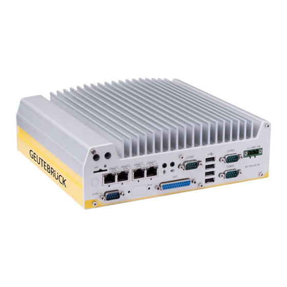
Device description Device description Overview G-ST 500+ Recommended uses and applications The G-ST 500+ is specially designed for use in all types of vehicles. Forklift trucks, trucks, buses, money transporters, taxis, VIP or police vehi- cles, ships as well as sea containers can be monitored from a central location. -
Page 7: Transportation, Storage, Initial Commissioning
Device description Transportation, storage, initial commissioning Transportation and storage The device is shipped from the factory in a shipping box with a special cush- ion packing. This protects the device from damage during transportation. Whenever possible, use the original device packaging. Transportation and storage conditions Temperature range: -25°C to +70°C ... -
Page 8: Device View
Device description Device view Front view Figure: Front view G-ST 500+/8R Rear view Figure: Rear view G-ST 500+/8R Figure: Rear view G-ST 500+/4M V 1.0... -
Page 9: Front Panel I/O Functions
Device description Front Panel I/O Functions On G-ST 500+, plenty of I/O functions are provided on front panel and back panel so you can easily access them. Most common computer I/O functions are placed on the front panel. In this section, we’ll illustrate each I/O function on the front panel. - Page 10 Device description 1 DisplayPort Connectors The system has dual DisplayPort (DP) outputs which are digital display interfaces that mainly connect video source and carry audio to a display device. When connecting a single DP, it can deliver up to 4096 x 2304 resolution and each port can deliver up to 2880 x 1800 resolution when both DPs are connected in conjunction.
- Page 11 Device description 3 VGA-Connector VGA connector is the most common video display connection. The VGA output supports up to 1920x1200@60Hz resolution. By default, the VGA output is set to “always-on”. For users who want to use only digital display interface (eg. DVI or DP), the VGA Output setting can be disab- led.
- Page 12 Device description 5 GbE RJ-45 Network Connections / PoE The G-ST 500+/4RJ45 and G-ST 500+/M12X offer two GbE ports (1+2 in red and blue) while 500+/8RJ45 has four additional PoE (Power over Ethernet) ports marked 3 in green on the front panel.
- Page 13 Device description 6 On/ off control & status output The “On/ Off Control Ctrl & Status Output” connection allows for external switch and LED in- dicator extension. It is useful when the system is placed in a cabinet or a not easily acces- sed location.
- Page 14 Device description 8 System Status LED There are four LED indicators on the front panel: PWR, HDD, WDT and IGN. The descriptions of these four LEDs are listed in the following table. Indicator Color Description Green Ignition signal indicator, lid when IGN is high (12V/ 24V). Yellow Watchdog timer indicator, flashing when WDT is active Hard drive indicator, flashing when SATA drive is active...
-
Page 15: Rear View
Device description Rear view Back Panel I/O Functions To fit more general application requirements, G-ST 500+ offers more I/O functions on its back panel. In this section, we’ll illustrate each I/O function on the back panel. Item Description With a 3G/ 4G module installed, insert a SIM card to access SIM card slot the operator‟s network. - Page 16 Device description 1 SIM Card Slot On the rear panel, there is a panel-accessible SIM socket. By installing a 3G/4G module onto the internal mini-PCIe port, you can have Internet access via telecom operator‟s network. The SIM socket is a push-push type. The push-push mechanism means the SIM card is push-to-in- stall and push-to-retrieve.
- Page 17 Device description 4 RJ-45 Power over Ethernet Port PoE ports are provided via RJ-45 connectors. Power over Ethernet (PoE) is an Ethernet technology that supp- lies electrical power along with data on a standard CAT-6 Ether- net cable. When plugged in, the Ethernet connection status and speed are shown on RJ45 LED indicators.
- Page 18 Device description M12 Power over Ethernet Port (G-ST 500+/M12X) M12 socket (panel side) M12 plug (cable side) M12 Pin and Corresponding RJ45 Wire Connection Wire color Signal M12 Pin RJ45 Wire orange orange green blue blue green brown brown V 1.0...
- Page 19 Ethernet devices. 6 Microphone-in 3.5mm Jack 8 Speaker-out The audio function on G-ST 500+ series uses Intel® High Definition Audio in Q170 chipset and Realtek ALC262 codec. There are two audio function jacks, the port is used for microphone input, and the port is used for speaker / headphone output.
- Page 20 Device description 7 Digital Input/ Output The system provides 4x isolated digital input channels and 4x isolated digital output channels. The DIO functions support polling mode I/O access and DI change-of-state interrupt. Please refer to Watchdog Timer & Isolated DIO for information on wiring and programming the isolated DIO channels.
- Page 21 Device description 9 COM Ports The system has three COM ports for communicating with external devices. COM1, COM2 and COM3 ports are located on the rear panel via 9-pin D-Sub male connectors. They are implemented using industrial-grade ITE8786 Super IO chip (-40 to 85°C) and provide up to 115200 bps baud rate.
-
Page 22: Internal I/O Functions
Device description Internal I/O Functions In addition to I/O connectors on the front/back panel, G-ST 500+ provides other useful features via its on-board connectors, such as mini-PCIe sockets. In this section, we’ll illustrate these in- ternal I/O functions. Dual Mode mSATA/ mini-PCIe socket G-ST 500+ provides a dual mode mSATA/ mini-PCIe socket that is in compliance with mini- PCIe specification rev. - Page 23 Device description mini-PCIe Socket This mini-PCIe socket works in cooperation with the panel-accessible SIM slot. By installing a mini-PCIe module, you can add additional features to your system such as WIFI, GPS, CAN bus, analog frame grabber, etc. You can also install a 3G/4G module and SIM card for internet via your service provider‟s 3G/ 4G network.
-
Page 24: Install Mini-Pcie Module
Device description Install Mini-PCIe Module Disassembling the System Enclosure 1. Turn the system upside-down. 2. Unscrew the six (6) screws indicated below on the front panel. 3. On the rear panel, remove the six (6) screws indicated. 4. Gently lift the bottom enclosure cover and disconnect any cables connected to the rear pa- nel. - Page 25 Device description mini-PCIe Module Installation There are two full size mini-PCIe sockets with SIM card support on the PCBA and another two on the MezIO module. It supports off-the-shelf mini-PCIe modules. Please refer to the following procedures on how to install a mini-PCIe module. WARNING It is recommended to install 4G SIM mini-PCIe modules onto the MezIO module‟s mini-PCIe...
- Page 26 Device description 4. Clip on the IPEX-to-SMA cable to the module and attach the antenna onto the front or rear panel. Clip on IPEX-to-SMA cable Attach antenna to panel 5. Insert the SIM card (if necessary) situated underneath the mini-PCIe slot on the MezIO module.
-
Page 27: Connect To The Internet
Device description Connect to the Internet Step 1 Open the settings. Step 2 Select Network and Internet. Step 3 Click on Cellular (A) and click at the corresponding connection on Connect (B). Step 4 Enter the PIN (A) of your SIM card. Then confirm with Next (B). -
Page 28: Setting Up Apn (Access Point Name) For Cellular Manually
Device description Setting up APN (Access Point Name) manually Usually, Internet access is set up automatically when you start using your device. If your device was not set up successfully, you can set up Internet access manually. Step 1 Open the Settings. Step 2 Select Network and Internet. -
Page 29: Installing A Half Size Mini Pcie Module
Device description Installing a Half Size mini PCIe Module If you want to install a halfsize module (e.g. WIFI card), you will need the following mounting adapters and accessories: - 1 x 4.94437 Metal adapt half size MiniPCIe - 2 x 4.94421 RF-Interface Cable 'IPEX U.FL' to 'SMA' DC Power Connection... -
Page 30: Mounting Of Your G-St 500
Device description Mounting of your G-ST 500+ G-ST 500 series is shipped with dedicated wall mount/ anti-vibration for in-vehicle installation. The patented anti-vibration damping bracket offers superior vibration resistance (up to 1Grm with HDD and 5Grms with SSD, operating). To install the bracket, please refer to the following installation procedure. - Page 31 Device description Mount your G-ST 500+ on the Wall/Surface The included bracket can also be wall mounted. To install the system as a wall mount device, please refer to the following illustration. 1. Take the anti-vibration damping bracket, four (4) M4 step screws and four (4) shock-absor- bing grommets from the accessory box.
- Page 32 Device description Mount your G-ST 500+ on the DIN Rail The system also comes with an optional DIN-rail mounting kit. The kit includes a bracket and a DIN-rail mounting clip. By fixing the clip to the bracket using four M4 flat-head screws and fixing the bracket assembly to the system four M4 screws, complete the installation by clipping the system onto the DIN rail.
-
Page 33: Turning On The Device
Device description Turning on the device Before turning the unit on, please observe the following safety information. Ensure a power between 8 VDC and 35 VDC. Please do not press any keys while powering up! The operating system is precisely pre-configured for your device. By press- ing a key during powering up, this configuration could be adversely affected. - Page 34 Device description Powering On Using External Non-latched Switch If your application demands the system to be placed inside a cabinet, you may use an external non-latched switch to power on/ off the system. The system provides a “On/ Off Control Ctrl & Status Output”...
- Page 35 Device description Wait until the operating system has started up and the Begin Registration window is dis- played. During this operation, the client and the database of the device are started automati- cally. Use the key combination Ctrl +Alt +Del to log on MS Windows. Enter the following at the MS windows Logon dialog box: User name: Administrator...
-
Page 36: Integrating The Device Into The Network
Device description To modify the language displayed in Windows, follow these steps: Add the desired language. Define the desired languages as the primary language. Double click on the Language icon and click "Install display languages" to open the selec- tion menu. -
Page 37: Working With The G-St 500
Working with the G-ST 500+ Working with the G-ST 500+ Overview After the G-ST has been started and successfully integrated into a network, you can work with the device. The G-ST uses the following applications which can be opened using the start bar or from the desktop using a double click: G-Set is the G-ST setup client. - Page 38 Working with the G-ST 500+ In G-Set, you will perform, among others, the following tasks to set up the system: Register all IP cameras that are integrated in the network with your G-ST. Set up the media channels. For each media channel the quality pro- ...
-
Page 39: Using The Online Documentation
Working with the G-ST 500+ Using the online documentation All necessary functions for set up and configuration of the system are de- scribed in the G-Set Online help. You will also find the details of the G- View operating component. You open the integrated Online help using the Help menu in the menu bar of the open programs G-Set or G-View or with double click on the desktop icon. -
Page 40: Managing I/O Contacts
Working with the G-ST 500+ Managing I/O contacts Using programmable and tamper-monitored digital inputs and outputs, con- tacts for event-controlled recording can be controlled. For example, using a contact the movement of a pan/tilt head can be triggered, a gate can be opened or an infrared light can be switched on. -
Page 41: Turning Off The Device
Working with the G-ST 500+ 4. Assign for each required input and output contact a descriptive name and enter an additional description. Turning off the device To turn off your G-ST, proceed in the following order: 1. Close all applications and click Start in the taskbar. 2. -
Page 42: Driver Installation
Working with the G-ST 500+ Driver Installation Geutebrück provides a very convenient utility in “Drivers & Utilities DVD” to allow the “One-Click” driver installation. This utility automatically detects your Windows operating system and installs all necessary drivers to your G-ST 500+ with just one mouse click. Install All Drivers Using “One-Click”... -
Page 43: Resetting The System To Factory Settings
Resetting the system to factory settings Resetting the system to factory settings Recovery DVDs are provided with your device. This allows for the recovery of the software in- stalled at delivery as well as the original settings. Please note that the recovery process should only be carried out by qualified personnel, as all data on the C:\ drive will be overwritten! Back up your settings on an external disk beforehand. - Page 44 Resetting the system to factory settings 6. In the menu "Troubleshoot" click on the menu button " GEUTEBRUECK Recovery Solution ". 7. Select the size of the Windows partition, click RECOVERY START 8. Confirm disk partition by clicking YES. Now the system recovery starts. During the recovery process, the device may be rebooted several times.
-
Page 45: Appendix
Appendix Appendix Technical data Operating System Windows 10 IoT Enterprise Embedded Max. IP video sources 32 via G-Core/CamConnect Resolution FullHD Max. Database 4 TB Compression M-JPEG, H.264, H264CCTV, ready for H.265 Database architecture Dual for image and process data CPU type 1 x i3 integrated PoE Ports 4 / 8... -
Page 46: Mechanical Dimension
Appendix Mechanical Dimension Views of G-ST 500+ Dimensions with Mount Bracket/ Anti-vibration Grommet V 1.0... -
Page 47: Regulation
Appendix Regulation This device complies with Part 15 of the FCC Rules. Operation is sub- ject to the following two conditions: (1) This device may not cause harmful interference, and (2) this device must accept any interference received, including interference that may cause undesired operation. Please note that depending on the equipment of the 'G-ST 500+' with radio modules, special antenna cables or antennas, the requirements for compliance with the Euro-... - Page 48 GEUTEBRÜCK GmbH Im Nassen 7-9 | D-53578 Windhagen Technische Änderungen vorbehalten. Tel. +49 (0)2645 137-0 | Fax-999 Technical alterations reserved. info@geutebrueck.com Sous réserve des modifications. www.geutebrueck.com Suministro sujeto a modificaciones técnicas o disponibilidad.
Need help?
Do you have a question about the G-ST 500+ Series and is the answer not in the manual?
Questions and answers