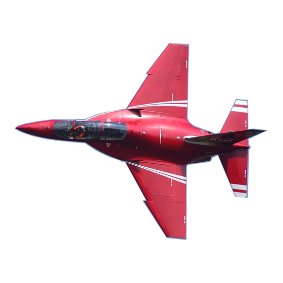
Summary of Contents for C&C Models AERMACCHI M346
- Page 1 C&C MODELS AERMACCHI M346 Building instructions rev1.2 Pag 1 AILERON AND FLAP SERVOS INSTALLATION...
- Page 2 In the hardware package you will find the servo wood blocks (8 pcs,bag H).Screw the servo to two blocks and check the correct position on the servo plate. Then secure the blocks to the plate with CA glue. It is highly recommended to screw the block from outside of servo cover. We also recommend to use strong servos.
- Page 3 Pag 3...
-
Page 4: Rudder Servo Installation
RUDDER SERVO INSTALLATION You will find the servo support inside the rudder, simply screw the servo in place and make a slot for the servo arm. Check out the correct position for the linkage (bag C) and check where you have to make the slot for the control horn (bag C).We recommend to use a strong servo (JR8711 or similar) Pag 4... - Page 5 Pag 5...
- Page 6 Pag 6...
-
Page 7: Elevator Servos Installation
ELEVATOR SERVOS INSTALLATION Elevator servo support is ready to use. Before you glue it, check carefully the servo installation and movements. Put the two elevator carbon rod in the bearing support,align and screw it. USE LOCKTITE! Screw the two servos (jr8911 or similar) to the support (part F) and glue it to the former in the fuselage, we recommend to glue this part very carefully and strong using good epoxy resin. - Page 8 GEAR DOORS INSTALLATION You can choose to install servos or air cylinders for the gear doors movements. Three hinges are used for the main gear doors. (not included in the kit) For the small doors and the nose doors use the brass hinge(not included in the kit) Pag 8...
- Page 9 ATTENTION: YOU CAN CHOISE TO INSTALL BRASS HINGES OR PLASTIC HINGES. THESE PARTS ARE NOT INCLUDED IN THE KIT. Pag 9...
- Page 10 To simplify the gear door system you can also choose to screw the two small main gear doors and cutting a slot in it for the leg. If you choose to install servos for the gear door movement, in the hardware package (bag A+M) you will find the servo supports shown in the picture below.
- Page 11 TURBINE AND PIPE INSTALLATION Turbine support and pipe are ready to use. But before mounting it finally please check the correct position from the turbine and pipe to the fuselage. Pag 11...
- Page 12 For safety we highly recommend to protect the exhaust area and the bottom of the elevators with aluminium sheets like shown on the pictures below. Pag 12...
- Page 13 In the kit you will find the inox protection for the exhaust area on the fuselage, sand it and glue in position, for safety stop with some small screws. Pag 13...
-
Page 14: Fuel Tank Installation
RETRACTS INSTALLATION Our retract kits are ready to use, you just need to screw the retracts to the wood support and check the correct movement together with the gear doors. FUEL TANK INSTALLATION The main fuel tank must be positioned on top of the air inlet. You have to glue the two wood supports (included in a hardware bag M) to the tank, using a strong epoxy resin. - Page 15 Cover of main fuel tank is painted with graphite spray(not included in the kit) Hopper tank position next to the main tank...
- Page 16 Pag 15 The wood plate (O) should be used to install electronic devices. In our model for we simple covered the plate with Carbon Oracover film.
- Page 17 Pag 16 Fuel pump, filter and valve position next to the turbine using wood plate N. Wood rib G is used as support. Glue it through the main gear door to the tank.
- Page 18 Pag 17 How to secure the wings The two carbon spars on the wings are secured trough the aluminium blocks which are already fixed in the correct position. Main screws trough the gear doors, for rear screws you have to drill holes in the fuselage.Please check the screws of aluminium block and screw it if need.
- Page 19 Pag 18 Drill holes for the two pins into the bottom of turbine cover and put the horns from the airbrake in it. You can run the airbrake with servo or air cylinder at your choice. Center of gravity The center of gravity is located from 21 to 23 cm from the leading edge!You can settle it at 21-22 cm for the first flight,the model result more stable.
- Page 20 Throws Aileron:15 mm up 15 mm down, expo 60% Elevator: 35 mm up 30 mm down, expo 60% Flap: take off 15 mm Rudder:20mm left/right In the starting sequence of your turbine we recommend to move the elevators like in the picture below to avoid problems with high temperature during startup.
- Page 21 Package contains: 1 pcs Fuselage 1 pcs Nose 1 pcs Canopy 1 pcs Turbine cover A couple of Wings 2 pcs elevators 1 pcs Rudder and fin 2 pcs big main gear doors 2 pcs small main gear doors 1 pcs nose gear door 1 pcs rear fuselage/servo cover Hardware bag contains: 1 pcs electronic wood plate...
- Page 22 To simplify the main gear doors it’s possible to glue the big with a small like in the photo below TWO SMALL SERVOS FOR THE NOSE GEAR DOORS...
- Page 23 STEERING SERVO C&C MODELS ITALY...


Need help?
Do you have a question about the AERMACCHI M346 and is the answer not in the manual?
Questions and answers