
Summary of Contents for RGBlink CP 3072
- Page 1 CP 3072 User Manual Manual #: RGB-RD-UM-CP3072 E001 Revision: V1.1 This User Manual Applies to CP 3072 and CP 3072S! CP 3072 User Manual...
- Page 2 Technology Co.,LTD. No part can be copied, reproduced or translated without permission. Notice RGBlink provides this manual “as is” without warranty of any kind, no matter expressed or implied, including but not limited to the implied warranties or merchantability and fitness for a particular purpose. RGBlink may make improvements or changes to the products and the programs described in this publication at any time without notice.
- Page 3 30 days after the transfer of risks. In the event of justified notice of compliant, RGBlink can repair the fault or provide a replacement at its own discretion within an appropriate period. If this measure proves to be impossible or unsuccessful, the purchaser can demand a reduction in the purchase price or cancellation of the contract.
- Page 4 Company Address Xiamen RGBlink Science & Technology Co., Ltd. S603~604 Weiye Building Torch Hi-Tech Industrial Headquarter: Development Zone Xiamen, Fujian Province, P.R.C Floor 11, A1 Building, Baiwang R&D Building, Shenzhen office: Shahe West Road, Xili Town, Nanshan District, Shenzhen, Guangdong Province, P.R.C No.
- Page 5 To avoid fire hazard, use only the fuse having identical type, voltage rating, and current rating characteristics. Refer fuse replacement to qualified service personnel. Do Not Operate in Explosive Atmospheres To avoid explosion, do not operate this product in an explosive atmosphere. CP 3072 User Manual...
- Page 6 Highlights an essential operating procedure, condition or statement. CAUTION The exclamation point within an equilateral triangle is intended to alert the user to the presence of important operating and maintenance (servicing) instructions in the literature accompanying the appliance. CP 3072 User Manual...
- Page 7 Time ECO# Description Principal V1.0 2015-03-30 0000# Release Vira V1.1 2015-06-01 0001# 1. Add SDI input module. Vira 2. Update the menu. 3. Update the common questions. 4. Add “Solution for weak damping effects of T-bar”. CP 3072 User Manual...
-
Page 8: Table Of Contents
System Overview ................20 Application Questions ................. 21 2. Hardware Orientation ..............22 In This Chapter ................. 22 CP 3072 Back Panel ................ 23 CONT Interface ..................23 19: Dial Switch ..................23 20: USB Interface ..................24 21. 22: RS-232 Interface ................. 24 INPUT Interface .................. - Page 9 Switch and Power ..................26 17. 18: Switch and Power ............... 26 TALLY Light ....................26 24: TALLY Light ..................26 CP 3072 Front Panel ............... 27 PVW Out Area ..................28 Save/Load Area ..................29 Function Edit Area..................30 Input Source Edit Area ................
- Page 10 Interface and Input Signal Option ........... 45 How to Change the Transition Effects..........47 How to Choose the Output Format ..........48 How to Edit the Channel Signal ............49 How to Realize Single Image Switching ........50 CP 3072 User Manual...
- Page 11 No Sound Output from Output Port ..........62 Confirm if the DVI Mode of PGM Output is HDMI ......62 VGA Input Offset or cannot be Full Size Shown ......62 Set Auto Adjust for VGA Input ..............62 CP 3072 User Manual...
- Page 12 A. Specification ................63 B. Contact Information ..............66 C. Software Upgrade ..............67 D. Solution for Weak Damping Effects of T-bar ......72 CP 3072 User Manual...
-
Page 13: Brief Introduction
Brief Introduction This chapter is designed to introduce you to the CP 3072 User Manual. Areas to be covered are: Chapter Structure How to Use the Manual Terms and Definitions System Overview Application Questions CP 3072... -
Page 14: Chapter Structure
1. Brief Introduction Chapter Structure Chapter Structure The following chapters provide instructions for all aspects of CP 3072 operations. Chapter 1 Brief Introduction Chapter 2 Hardware Orientation Chapter 3 Hardware Installation Chapter 4 Menu Orientation Chapter 5 System Setup and Operations... -
Page 15: How To Use The Manual
For system setup and operations, refer to Chapter 5, “System Setup and Operations” on page 44. Should you have any questions regarding the installation or operation of CP 3072, please consult with the factory. Refer to Appendix B on page 66 for contact information. CP 3072... -
Page 16: Term And Definitions
The source device will then output the optimal video format for the display based on the provided EDID data, ensuring proper video CP 3072 User Manual... - Page 17 525 lines of resolution with a refresh rate of 60 fields per second (60 Hz). Each frame is comprised of two fields of 262.5 lines each, running at an effective rate of 30 frames per second. CP 3072 User Manual...
- Page 18 “SDI”: Serial Digital Interface. The standard based on a 270 Mbps CP 3072 User Manual...
- Page 19 60 Hz (Mode 3). The signal is non-interlaced in modes 1, 2, and 3 and interlaced when using the 8514/A card (35.5 kHz, 86 Hz) in mode 4. It has a pixel by line resolution of 640×480 with a color palette of 16 bits and 256,000 colors. CP 3072 User Manual...
-
Page 20: System Overview
1. Brief Introduction System Overview System Overview CP 3072 is a multiviewer and presentation mixer with multi-layers preview function that support analog and digital video graphics to be mixed together and seamlessly switched to program outputs. User can realize the switching effects by using the interactive control panel, including the buttons, knobs, T-BAR, slider control, OLED panel, the indicator light etc. -
Page 21: Application Questions
1. Brief Introduction Application Questions Application Questions RGBlink offers solutions to demand technical problems. Any application questions, or required further information, please contact with our Customer Support Engineers. Refer to Appendix B for contact details. (CP 3072 System Connection Diagram) -
Page 22: Hardware Orientation
Hardware Orientation In This Chapter This chapter provides detailed information about the CP 3072 hardware. The following topics are discussed: CP 3072 Back Panel CP 3072 Front Panel CP 3072 User Manual... -
Page 23: Cp 3072 Back Panel
2. Hardware Orientation CP 3072 Back Panel CP 3072 Back Panel The figure below illustrates the professional interface and control signals of CP 3072 back panel. INTERFACE INTERFACE 1. 5. 9. 13 USB input USB-B port 23. 25 Audio input port 2. -
Page 24: 20: Usb Interface
It includes 4 CVBS inputs by BNC port, 4 USB inputs, 4 HDMI inputs (only for CP 3072), 4 3G-SDI inputs (only for CP 3072S), 4 VGA inputs by DB15 port, and 1 group of Audio L and Audio R input. -
Page 25: 2. 6. 10. 14: Cvbs Input
2. Hardware Orientation CP 3072 Back Panel 2. 6. 10. 14: CVBS Input CVBS input, input standard video signal from players, cameras etc. Support resolution 480i and 576i via BNC. Support standards include: PAL and NTSC. 3. 7. 11. 15: HDMI/3G-SDI Input HDMI input, input the image signal from computer. -
Page 26: 30: Hdmi Pvw Output
2. Hardware Orientation CP 3072 Back Panel Connect to the monitor or LED display which has VGA interface. (This VGA connector does not support hot-plugging) 30: HDMI PVW Output HDMI output interface, used to connect to the display device, video processor or matrix. -
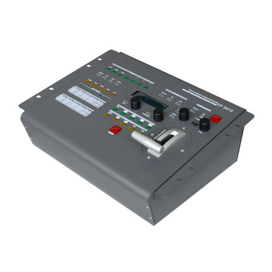
Page 27: Cp 3072 Front Panel
CP 3072 Front Panel CP 3072 Front Panel Plug into the power cord, OLED panel on the front panel will show RGBlink and go into self verification before it load last setting and send processed image to the target monitor. For the first setup, HDMI input is default source. -
Page 28: Pvw Out Area
2. Hardware Orientation CP 3072 Front Panel CP 3072 front panel is as following: Panel Instruction PVW out area Output format setting area Save/Load area Lock top panel area Function edit area Transition time control area Input sources edit area... -
Page 29: Save/Load Area
2. Hardware Orientation CP 3072 Front Panel Program output signal, push the button, the button light is on, and PVW out will be switched to this channel. Save/Load Area Load button, push the button, and combined with PAGE button to load the saving parameters, users can load data from SAVE1 or SAVE16. -
Page 30: Function Edit Area
2. Hardware Orientation CP 3072 Front Panel Function Edit Area OLED Panel, used for show button menu and menus for interactive communication. Knob, used to adjust OLED menu and information interaction and with the same function with enter to confirm current options. -
Page 31: Input Source Edit Area
SDI signal source button, push the button, the signal will be edited to preview channel. For CP 3072, the OLED screen will remind: CP 3072 standard version! There is no SDI input module, Any question, please contact: 4008-592-114... - Page 32 2. Hardware Orientation CP 3072 Front Panel Reuse button 1: In one window mode, it is the output indicator button. In PIP mode, push the button, the preview sub-image signal will be switched to this channel. In adjustment mode, it is the number reuse button.
-
Page 33: Dsk, Blend And Pip Area
2. Hardware Orientation CP 3072 Front Panel Reuse button 3: In one window mode, it is the preview edit channel indicator button. In PIP mode, push the button, the preview will be switched to this channel. In adjustment mode, it is the number reuse button. -
Page 34: Effects Operation Area
2. Hardware Orientation CP 3072 Front Panel PIP function button: Single or dual image selection button, push the button, its LED light turns on, PIP function is open. Push the button again, its LED light turns off, PIP function is close, and return to single image. -
Page 35: Output Format Setting Area
Output Format Setting Area Output format button. Push the button to enter to the output format, and turn the knob to choose the different output formats. CP 3072 supports 5 kinds of output formats, including: 1024×768@60, 1280×768@60, 1280×1024@60, 1440×900@60, 1920×1080@60. -
Page 36: Transition Time Control Area
2. Hardware Orientation CP 3072 Front Panel Transition Time Control Area OLED panel: Show the transition switch time. TIME knob, turn the knob to adjust the transition time. T-bar Control Area T-bar switcher, choose the effect modes, and then push the T-bar switcher up or down to switch the effects to output. -
Page 37: Hardware Installation
In This Chapter This chapter provides comprehensive installation instruction for CP 3072 hardware: CP 3072 is specified fight case packing, and following are the size of CP 3072 (Figure 1) and fright case (Figure 2) for your reference. (Figure 1) (Figure 2) -
Page 38: Safety Precautions
2 HDMI to DVI cables, 1 U disk and 1 parts bag, which include 1 PVC bag, 1 CP 3072 silkscreen, 1 standard screwdriver, 2 blank key caps and 2 T-bar gasket. If you find any shortages, contact your sales representative. -
Page 39: Menu Orientation
Menu Orientation In This Chapter This chapter describes all CP 3072 processor menus, including how they are accessed, the functions that are available, and descriptions of each menu tree (in block diagram format). The following topics are discussed: • MENU ... -
Page 40: Menu
AUTO ADJUST: Auto adjust VGA input signal H POS, V POS, CLOCK, PHASE, auto adjust to display in full screen image. Note Comments customers to use this operation in adjusting the VGA input shiftment. H POS: Image horizontal position. V POS: Image vertical position. CP 3072 User Manual... -
Page 41: Output
RESET: If image quality distorts by improper operation, it can be recover by reset. 3. OUTPUT DETAIL: Output detail menu, the sub-menu as following: FORMAT: Show the current output format. DVI MODE: Show the DVI mode. DATE RANGE: Show the date range as VIDEO or IMAGE. CP 3072 User Manual... -
Page 42: System
MCU VER: Information of MCU version. VIDEO VER: Information of VIDEO version. FPGA VER: Information of FPGA version. SN: Factory serial number of CP 3072. TECH SUPPORT: Including sales hotline, custom service, web site, email and telephone. DATE&TIME: Display date or time, including the following items: DATE: Display date. -
Page 43: Language
FACTORY RESET Enter FACTORY RESET to reset the device, choose YES and push the knob to confirm, then CP 3072 is reset to its factory settings. It is ready for more operations after completing factory setting. CP 3072... -
Page 44: System Setup And Operations
How to Set up the PIP How to Use Black Out How to Realize the BLEND Setting How to Realize the DSK Setting How to Save the Parameter How to Load the Saved Parameter CP 3072 User Manual... -
Page 45: Interface And Input Signal Option
29. VGA program output, connect to monitor or projector which with VGA interface. Support the following output resolutions: 1024×768@60, 1280×768@60, 1280×1024@60, 1440×900@60, 1920×1080@60. 31. CVBS Program output, connect to TV, and the device with CVBS input. CP 3072 User Manual... - Page 46 3. 7. 11. 15. HDMI Input, input the video signal from HD player, DVD, computer, set top box and hard disk, etc. (Only for CP 3072) 3. 7. 11. 15. 3G-SDI Input, input video signal from HD camera and radio processing equipment, connect SDI interface via 75 ohms impedance BNC port.
-
Page 47: How To Change The Transition Effects
Push the wipe pattern shortcut button , user can choose fade in fade out mode. 2. Push the [TAKE] button, or use T-bar switcher to switch between the image with effects. Note: T-bar is only available for fade. CP 3072 User Manual... -
Page 48: How To Choose The Output Format
OUTPUT FORMAT >1920×1080@60 2. Turn the knob and choose the output format according to actual need, for example, choose 1024×768@60: OUTPUT FORMAT *1024×768@60 3. Push the knob to confirm. OUTPUT FORMAT >1024×768@60 CP 3072 User Manual... -
Page 49: How To Edit The Channel Signal
2. Push any signal button in Input Sources Edit Area, For example, push [VGA] button, then the signal of channel 2 will be switched to VGA. B-BUS INPUT : INPUT 2 INPUT SOURCE: VGA RESOLUTION : NO INPUT CP 3072 User Manual... -
Page 50: How To Realize Single Image Switching
How to Realize Single Image Switching How to Realize Single Image Switching CP 3072 can realize seamless effects switch between two channels, choose the channel in B-BUS/PST area, then push the [TAKE] button, the signal will be switched to LED display. -
Page 51: How To Scale The Image
3. If image quality distorts by improper operation, it can be recover by reset. >H SIZE 1920 V SIZE 1080 RESET CP 3072 User Manual... -
Page 52: How To Crop The Image
3. If image quality distorts by improper operation, it can be recover by reset. >H SIZE 1024 V SIZE H POS V POS >RESET CP 3072 User Manual... -
Page 53: How To Set The Position Of The Image
User can adjust the items by the knob or number buttons, after setting, push the knob to confirm. 3. If image quality distorts by improper operation, it can be recover by reset. >H POS V POS RESET CP 3072 User Manual... -
Page 54: How To Set Up The Pip
R+B, PIP CENT, PBP L+R and PBP T+B. Take 3 results for example, shown as follows: PIP L+T PBP L+R PBP T+B SELECT: Choose the channel for operation, user can choose the channel of A BUS or B BUS. CP 3072 User Manual... -
Page 55: How To Use Black Out
Black out descriptions: Black signal realizes one-key-touch to a black screen. CP 3072 provides black effect processing for program output and preview output, with cut black effect. Operation is as below: Push the [BLACK] button in A-BUS/PGM bar, the button light is on, then the program output is cut to black. -
Page 56: How To Realize The Blend Setting
Turn the knob, choose “ON”, push the knob to confirm. 4. Turn the knob, and choose <BLEND WIDTH>, push the knob to confirm. Turn the knob to set the blend width. 5. If image quality distorts by improper operation, it can be recover by reset. CP 3072 User Manual... -
Page 57: How To Realize The Dsk Setting
Suggest priority setting of Y offset. If image quality distorts by improper operation, it can be recover by reset 3. Turn the KEY LEVEL knob to set the Alpha, the adjustment range is 0 to 100. CP 3072 User Manual... -
Page 58: How To Save The Parameter
How to Save the Parameter How to Save the Parameter There are 4 pages and each page has 4 save modes, CP 3072 provides 16 save modes. 1. Push the [SAVE] button, the button light turns on, and PAGE, 1, 2, 3 and 4 button lights flash. -
Page 59: How To Load The Saved Parameter
How to Load the Saved Parameter How to Load the Saved Parameter There are 4 pages and each page has 4 save modes, CP 3072 provides 16 save modes for load. 1. Push the [LOAD] button, the button light turns on, and PAGE, 1, 2, 3 and 4 button light flash. -
Page 60: Common Questions And Solutions
The USB doesn't Play Video Well Flash Point in LED Display Output The HDMI Input Signal of Blu-ray DVD cannot be Shown No Sound Output from Output Port VGA Input Offset or cannot be Full Size Shown CP 3072 User Manual... -
Page 61: The Usb Does't Play Video Well
Confirm if There are Multiple Videos in USB Root Directory Pull out the USB from CP 3072 and plug in to the computer, check if there is video in USB root directory, do not save other non-video files at the same time. -
Page 62: No Sound Output From Output Port
Push the [MENU] button, then choose <INPUT>, turn the knob and choose <VGA ADJUST>, push the knob to confirm. Turn the knob and choose <AUTO ADJUST>, the auto adjust time is about 10 seconds. If auto adjust cannot solve the problem, please manually adjust in <VGA ADJUST>. CP 3072 User Manual... -
Page 63: Specification
USB Input Number of Inputs Connector Standard USB port Supported Standard Support general Image and video formats (CP 3072 V1.1 can only support video formats) HDMI Input (Only for CP 3072) Number of Inputs Connector HDMI standard type A interface Supported Resolution SMPTE: 625/25 PAL, 525/29.97 NTSC, 625/50p PAL,... - Page 64 VESA: 1024×768@60Hz, 1280×768@60Hz, 1280×1024@60Hz, 1920×1080@60Hz, 1920×1080@50Hz Signal Level R、G、B、Hsync、Vsync:0 to1Vpp±3dB (0.7V Video+0.3v Sync ) 75 ohm black level: 300mV Sync-tip: 0V HDMI PVW Output Number of Outputs Connector HDMI standard type A interface Supported Resolution 1024×768@60Hz CP 3072 User Manual...
- Page 65 Support PIP, PBP for any two inputs Audio sync switch support Extras Communication Top panel operation Power Supply 85-264V, IEC-3 Working Environment 0° C~45° C Stored Environment 10% to 90% Product Warranty 3-year parts and labor warranty CP 3072 User Manual...
-
Page 66: Contact Information
All video products are designed and tested to the highest quality standard and backed by a full 3-year parts and labor warranty. Warranties are effective upon delivery date to customer and are non-transferable. RGBlink warranties are only valid to the original purchase/owner. Warranty related... -
Page 67: Software Upgrade
Upgrade by “DfuSe Demonstration”, the form of the file is .dfu (as shown in Figure 1), and the upgrade steps are as follows: Figure 1 (1) Connect the USB interface of CP 3072 to the computer with a USB cable (as shown in Figure 2). Figure 2 (2) Dial the red dial switch behind the device upwards (as shown in Figure 3). - Page 68 (5) Click the button marked by green box after connection, choose the upgrade file, and click “Upgrade”, then pop up the confirmation window as shown in Figure 5, it will show as Figure 6 if upgrade successful. Figure 5 CP 3072 User Manual...
- Page 69 Upgrade by windows control program ”UpdateProgram.exe”, the form of the file is.bin.bin, and upgrade steps are as follows: (1) Connect the USB interface of CP 3072 to the computer with a USB cable. (2) Plug in the power cord, and make sure the device is in normal operation.
- Page 70 ( the form of the file is.bin.bin ), and click “Start” to upgrade core processing firmware. (5) When prompt “Down Load Success”, it means load is successful. (6) Reboot the device. CP 3072 User Manual...
- Page 71 Choose <INPUT 1> as the file, then choose <UPGRADE>, push the knob to upgrade USB 1, pull out the USB after finish, and insert the USB to the USB 2 port of CP 3072, boot the device, choose MENU-SYSTEM-UPGRADE-INPUT 2, then choose <UPGRADE>...
-
Page 72: Solution For Weak Damping Effects Of T-Bar
Solution for Weak Damping Effects of T-bar First, Remove the T-bar handle (unscrew loose): Remove the screw from the opposite side, and take the square silver box down: Remove the black oval plate: CP 3072 User Manual... - Page 73 Remove the four white screws, as shown below: Detach the block plate, remove the gaskets, and then remove the T-bar. Add a black gasket, a white gasket, as shown below: Install the T-bar, screw the two white screws first (fixed slightly): CP 3072 User Manual...
- Page 74 Straighten the T-bar, and add three gaskets as the following sequence: white, black, white. Screw and fasten all the three screws. Screw the oval plate again. CP 3072 User Manual...
- Page 75 Screw the square silver box from the opposite side, and then screw the handle. Above all steps are completed as following: CP 3072 User Manual...
Need help?
Do you have a question about the CP 3072 and is the answer not in the manual?
Questions and answers