Sign In
Upload
Download
Table of Contents
Contents
Add to my manuals
Delete from my manuals
Share
URL of this page:
HTML Link:
Bookmark this page
Add
Manual will be automatically added to "My Manuals"
Print this page
×
Bookmark added
×
Added to my manuals
Manuals
Brands
PRODEM Manuals
Power Tool
PRB008
Operation and maintenance manual
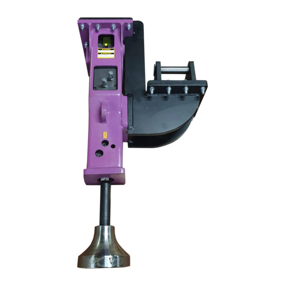
PRODEM PRB008 Operation And Maintenance Manual
Hydraulic hammers
Hide thumbs
1
2
Table Of Contents
3
4
5
6
7
8
9
10
11
12
13
14
15
16
17
18
19
20
21
22
23
24
25
26
27
28
29
30
31
32
33
34
35
36
37
38
39
40
41
42
43
44
45
46
47
48
49
50
page
of
50
Go
/
50
Contents
Table of Contents
Bookmarks
Table of Contents
Foreword
Table of Contents
1 Safety Information
Basic Safety Information
Preparation for Safe Operation
Safety Information on Safe Operating
Safety Information on Maintenance
2 Warranty
3 Product Information
Configuration of the PRODEM Hydraulic Hammer
Information for Ordering and Service
Markings and Labels
4 Technical Specifications
5 Installation
Carrier Requirements
Attaching the Mounting Adapter
Mounting the Hydraulic Hammer on the Carrier
Connecting the Hydraulic Lines of the Hammer
Connection Ports of the Hammer
Dismounting the Hydraulic Hammer from the Carrier
Fitting / Removing the Chisel
Adjusting the Pressure-Adjusting Valve
Adjusting Impact Rate - 2-Speed Selection
Anti-Blank-Blow (Auto-Stop) Function
Inspection after Installation
6 Operating the Hydraulic Hammer
Selecting the Right Chisel
Correct Working Methods
7 Maintenance
General Information
Care and Maintenance Schedule
Hydraulic Oil
Grease
Gas
Checking and Charging the Gas in the Back-Head
Checking and Charging the Gas in the Accumulator
Chisel, Wear Bushings and Chisel Pins
Bracket and Adapter
Screw Tightening
Replacing the through Bolts
Checking the Bottom of the Piston
Advertisement
Quick Links
1
Configuration of the Prodem Hydraulic Hammer
2
Fitting / Removing the Chisel
3
Gas
4
Checking and Charging the Gas in the Back-Head
Download this manual
Operation and Maintenance Manual
Hydraulic Hammers
PRB008
PRB 010
PRB 020
PRB 030
PRB 040(H)
PRB 050
PRB 060
PRB 100
PRB 150
PRB 170
PRB 200
PRB 250
PRB 300
PRB 400
PRB 500
PRB 700
Documents No.: AA099-0018
Revision Date: 2016-12-05
©PRODEM
Table of
Contents
Previous
Page
Next
Page
1
2
3
4
5
Advertisement
Table of Contents
Need help?
Do you have a question about the PRB008 and is the answer not in the manual?
Ask a question
Questions and answers
Related Manuals for PRODEM PRB008
Power Tool PRODEM PDS Series Operating Instructions Manual
Hydraulic hammer (48 pages)
Power Tool PRODEM PRB 030 Operation And Maintenance Manual
Hydraulic hammers (50 pages)
Power Tool PRODEM PRB 150 Operation And Maintenance Manual
Hydraulic hammers (50 pages)
This manual is also suitable for:
Prb 010
Prb 020
Prb 030
Prb 040
Prb 040h
Prb 050
...
Show all
Prb 060
Prb 100
Prb 150
Prb 170
Prb 200
Prb 250
Prb 300
Prb 400
Prb 500
Prb 700
Table of Contents
Save PDF
Print
Rename the bookmark
Delete bookmark?
Delete from my manuals?
Login
Sign In
OR
Sign in with Facebook
Sign in with Google
Upload manual
Upload from disk
Upload from URL


Need help?
Do you have a question about the PRB008 and is the answer not in the manual?
Questions and answers