Table of Contents
Advertisement
Quick Links
Advertisement
Table of Contents

Related Manuals for mikroElektronika SmartGLCD 240x128


Summary of Contents for mikroElektronika SmartGLCD 240x128
- Page 1 SmartGLCD...
- Page 2 TO OUR VALUED CUSTOMERS I want to express my thanks to you for being interested in our products and for having confidence in MikroElektronika. The primary aim of our company is to design and produce high quality electronic products and to constantly improve the performance thereof in order to better suit your needs.
-
Page 3: Table Of Contents
Table of Contents What is the SmartGLCD 240x128? step 5 – Uploading .hex file Package Contains step 6 – Progress bar 1. Key Features step 7 - Finishing upload System Specification Tips and Tricks: Speed-up UART data transfer 17 2. Power supply 6. -
Page 4: What Is The Smartglcd 240X128
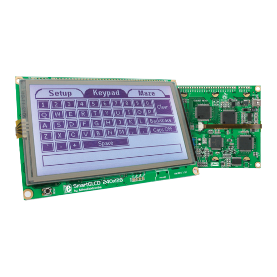
What is the SmartGLCD 240x128? The SmartGLCD 240x128 is a compact smart display, with many on-board peripherals. It’s designed to become a control interface of your device. Main part of the board is a large 240x128 pixel graphical LCD with a 4-wire resistive touch screen. -
Page 5: Package Contains
Digital Analog I/O mikroProg 240x128 We present you with a complete color schematics for SmartGLCD 240x128 development board. We want you to know what your board is consisted of and how it actually works. 3.3V power supply output 5V power supply... -
Page 6: Key Features
1. Key Features GLCD 240x128 display RESET button Power supply pads I/O pads Pads for mikroProg programmer USB connector Touch panel connector PIC18F87K22 microcontroler Contrast potentiometer microSD card slot USB UART module Buzzer Page 6... -
Page 7: System Specification
System Specification power supply Via USB cable (5V DC) power consumption ~350mA in idle state (backlight is ON) board dimensions 140x90cm (5.51x3.24’’) weight ~210g (0.46 lbs) Page 7... -
Page 8: Power Supply
2. Power supply The SmartGLCD board can be powered in two different ways: via USB connector (CN1) using MINI-B USB cable provided with the board (Figure 2-1), or via side headers (CN2 or CN4) using external 5V power supply (Figure 2-2 and Figure 2-3). Figure 2-1: Figure 2-2: Figure 2-3:... - Page 9 VCC-3.3 USB MINI-B VCC-MMC VCC-3.3 REG1 VOUT FERRITE MC33269DT-3.3 BEAD 100nF 100nF 47uF 10uF 10uF Figure 2-4: Power supply schematic Page 9...
-
Page 10: Pic18F87K22 Microcontroller
3. PIC18F87K22 microcontroller The SmartGLCD development tool comes with the PIC18F87K22 microcontroller. This 8-bit microcontroller is rich with on-chip peripherals and features 128KB of Flash and 4KB of RAM. It can easily handle demanding graphical applications. Key microcontroller features - Up to 12 MIPS Operation;... -
Page 11: Programming The Microcontroller
4. Programming the microcontroller Figure 4-1: PIC18F87K22 microcontroller The microcontroller can be programmed in two ways: Using USB UART mikroBootloader Using external mikroProg for PIC, dsPIC, PIC32 programmer ™ Page 11... -
Page 12: Programming With Bootloader
5. Programming with bootloader mikroBootloader software Microcontroller is preprogrammed with USB UART Bootloader, note which can be used to upload new device firmware. To trans- Before starting mikroBootloader software, connect SmartGLCD fer firmware .HEX file from a PC to MCU you need to use mikro- to a PC using a USB cable provided with the package. -
Page 13: Identifying Device Com Port
Identifying device COM port step 1 – Choosing COM port Figure 5-2: Identifying COM port Figure 5-3: Choosing COM port Click the Change Settings button. Port From the drop down list, select appropriate (in this Device Manager Ports Open window and expand Baud rate case it is COM18) and (115200). -
Page 14: Step 2 - Establishing Connection
step 2 - Establishing Connection step 3 - Browsing for .HEX file Figure 5-4: Connecting with mikroBootloader Figure 5-5: Browse for HEX Press Reset click Browse for HEX button on SmartGLCD board and Click the button and from a Connect within 5s, otherwise the existing microcontroller pop-up window (Figure 5-6) choose a .HEX file to be program will run. -
Page 15: Step 4 - Selecting .Hex File
step 4 – Selecting .hex file step 5 – Uploading .hex file Figure 5-6: Locating and selecting .hex file Figure 5-7: Begin uploading Open dialog Begin Select .HEX file from the window. In order to upload .HEX file click the uploading button. -
Page 16: Step 6 - Progress Bar
step 6 – Progress bar step 7 - Finishing upload Figure 5-9: Restarting MCU Figure 5-8: Progress bar Progress bar enables you to monitor .HEX file Click button after the uploading process has been uploading. finished. Reset Press button on SmartGLCD board and wait for 5 seconds. -
Page 17: Tips And Tricks: Speed-Up Uart Data Transfer
Tips and Tricks: Speed-up UART data transfer Right click on the USB Serial Port (COM18) item and then select Properties. note If .HEX file transfer from your PC to Select Port Settings tab. MCU is too slow, it’s possible to speed up data transfer by setting latency Click the Advanced... -
Page 18: Programming With Mikroprog ™ Programmer
6. Programming with mikroProg programmer ™ mikroProg The microcontroller can be programmed with the external programmer which can be connected to the board via CN3 ™ connector. Before establishing this connection it is necessary to solder 1x5 male header to CN3 connection pads. This can be done in both ways: on the bottom, or the top side, as shown in Figures 6-1 and 6-2. - Page 19 BAT43 mRST# mRST# MCLR PIC18F87K22 OSC2 VDDcore/Vcap OSC1 100nF Figure 6-3: mikroProg connection schematic ™ note Make sure to use only the front row of mikroProg’s IDC10 connector (side with a knob and incision) when connecting it to 1x5 header on your SmartGLCD board. Page 19...
-
Page 20: Mikroprog Suite ™ For Pic ® Software
7. mikroProg Suite for PIC Software ™ ® mikroProg programmer requires ™ special programming software called mikroProg Suite for PIC . It can be ™ ® used for programming all Microchip ® crocontroller families, including PIC10 ® PIC12 , PIC16 , PIC18 , dsPIC30/33 ®... - Page 21 Software Installation Wizard Start Installation Accept EULA and continue Install for all users Choose destination folder Installation in progress Finish installation Page 21...
-
Page 22: Microsd Card Slot
8. microSD Card Slot Figure 8-1: microSD card slot There is a built-in microSD card slot provided on-board. It enables the expansion of available memory space using microSD cards. Communication between the microcontroller and the card is done through Serial Peripheral Interface (SPI). Page 22... - Page 23 VCC-MMC microSD CARD MMC-CD# 100nF MCLR PIC18F87K22 OSC2 DAT0 VDDcore/Vcap OSC1 RC5-MOSI RC4-MISO RC3-SCK VCC-MMC VCC-3.3 REG1 VOUT FERRITE BEAD MC33269DT-3.3 100nF 100nF 47uF 10uF 10uF 100nF Figure 8-2: microSD Card Slot module connection schematic Page 23...
-
Page 24: Touch Screen
9. Touch Screen The development system features a Graphical LCD in 240x128 pixel resolution. Display is covered with a 4-wire resistive touch panel. Together they form a functional unit called a touch screen, Figure 9-1. It enables data to be entered and displayed at the same time. - Page 25 GLCD-FS BC556 BC546 GLCD-WR# GLCD-D2 RIGHT DRIVEA GLCD-CE# GLCD-D3 BC556 RA6963 GLCD DRIVEA CONTROLLER MCLR DRIVEB LEFT PIC18F87K22 OSC2 BC546 VDDcore/Vcap OSC1 100nF BOTTOM BC546 GLCD-D7 GLCD-D6 GLCD-FS DRIVEB 100nF TOUCH PANEL GLCD-MD 100nF CONTROLLER CONTRAST Figure 9-2: Touch Screen connection schematic Page 25...
-
Page 26: Rgb Backlight
10. RGB backlight Graphical LCDs are only capable of showing monochromatic pixel but not color content. The color of the pixel is determined by the color of the backlight which illuminates the display. SmartGLCD has RGB color backlight - a very useful feature which can give your graphical user interfaces an astonishing look. -
Page 27: Contrast Potentiometer
11. Contrast potentiometer On the backside of the board there is a small potentiometer which can be used to change Figure 11-1: contrast of the GLCD. The brighter the backlight, the Constrast less contrast you will need to properly display the potentiometer graphical content. -
Page 28: Usb Uart
USB-B connector (CN1) is used for connecting the USB cable, which is delivered with Copyright ©2011 Mikroelektronika. All rights reserved. Mikroelektronika, Mikroelektronika logo and other Mikroelektronika trademarks are the property of Mikroelektronika. All other tradmarks are the property of their respective owners. - Page 29 VCC-3.3 UART-TX OSCO 100nF DTR# OSCI RTS# TEST VCCIO AGND UART-RX 100nF CBUS0 CBUS1 MCLR PIC18F87K22 DSR# OSC2 VDDcore/Vcap OSC1 DCD# RESET# 10uF CTS# CBUS4 3V3OUT CBUS2 USBDM USBDP CBUS3 USBDP USBDM FT232RL MINI-B 100nF 100nF Figure 12-2: USB UART module connection schematic Page 29...
-
Page 30: Buzzer
13. Buzzer Figure 13-1: Buzzer module The board is also equipped with piezo buzzer. It is an electric component which can be used to create sound when provided with electrical signal. This is usually a PWM signal coming from a microcontroller pin. Before entering the buzzer itself, the signal is amplified by the on-board buzzer driver circuit. - Page 31 MCLR PIC18F87K22 OSC2 VDDcore/Vcap OSC1 BC546 100nF Figure 13-2: Buzzer module schematic Page 31...
-
Page 32: Pinout
14. Pinout C/SPI C/SPI Digital mikroProg Analog I/O Analog Lines Interrupt Lines SPI Lines I2C Lines UART lines 3.3V power supply output 5V power supply Ground Ground Page 32... -
Page 33: Dimensions
15. Dimensions 5512 4488 107.5 4232 16.3 11,6 12,7 12,7 11,56 4000 Legend active surface display margin display Pad hole size ø 1.14 mm ø 45 mils 13.12 12.57 1181 Mounting hole size ø 4 mm (79) ø 157 mils Tolerance +/- 0.5mm 5040 Page 33... -
Page 34: What's Next
GUI. It will automatically create necessary code which is compatible with mikroElektronika compilers. Visual GLCD is rich with examples, which are an excellent starting point for your future projects. Just load the example, read well commented code, and see how it works on hardware. - Page 35 No part of this manual, including product and software described herein, may be reproduced, stored in a retrieval system, translated or transmitted in any form or by any means, without the prior written permission of MikroElektronika. The manual PDF edition can be printed for private or local use, but not for distribution.
- Page 36 If you are experiencing some problems with any of our products or just need additional information, please place your ticket at www.mikroe.com/esupport If you have any questions, comments or business proposals, SmartGLCD 240x128 Manual ver. 1.51 do not hesitate to contact us at office@mikroe.com...
- Page 37 Mouser Electronics Authorized Distributor Click to View Pricing, Inventory, Delivery & Lifecycle Information: MikroElektronika MIKROE-762...
Need help?
Do you have a question about the SmartGLCD 240x128 and is the answer not in the manual?
Questions and answers