Table of Contents
Advertisement
Quick Links
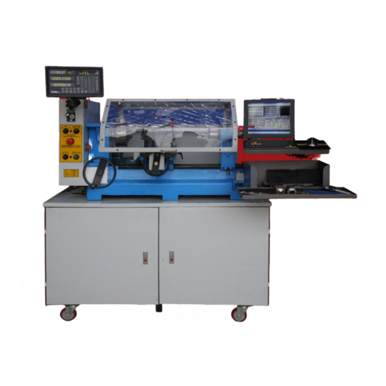
SHOPMASTER
SETUP MANUAL
Dear owner, thank you for choosing SHOPMASTER. This owner's manual is
being sent to you in .PDF format prior to the delivery of your machine so that you can
be prepared for it's setup upon arrival. As the owner, you may print out a hard copy of
this manual or have a bound copy done at a local office supply house for your personal
use. Copying or printing the manual for sale or distribution to others is prohibited.
INSPECTION OF CRATE UPON ARRIVAL
COPYRIGHT SHOPMASTER 1981-2017
DUPLICATION PROHIBITIED WITHOUT
WRITTEN CONSENT OF SHOPMASTER
Advertisement
Table of Contents

Subscribe to Our Youtube Channel
Summary of Contents for ShopMaster MILL TURN
- Page 1 DUPLICATION PROHIBITIED WITHOUT WRITTEN CONSENT OF SHOPMASTER Dear owner, thank you for choosing SHOPMASTER. This owner’s manual is being sent to you in .PDF format prior to the delivery of your machine so that you can be prepared for it’s setup upon arrival. As the owner, you may print out a hard copy of this manual or have a bound copy done at a local office supply house for your personal use.
-
Page 2: Assembling The Bench
Your machine will arrive at your destination by truck freight. The driver will ask you to sign the delivery slip. Before you sign, please inspect the crate carefully for any signs of rough handling such as holes, broken pieces etc. Because the machines travel a great distance from the factory to you, scuff marks, scratches and small chips in the crate are normal. - Page 3 control knobs. Once the leg assembly is clear of the machine, flip it over so that it is sitting on the 6 leveling pads. Be sure that it is resting solidly on the pads, not on the casters. Also be sure to orient the leg assembly so that when you lift the machine onto it, the front portion faces the front of the machine.
- Page 4 slipped into place. You can even use the crate material by gluing 2 panels together and stacking some cinder blocks on them while the glue dries and then cutting them to size. You can also buy drawer assemblies, or use one of those low cost toolbox units sold at discount stores placed inside the cabinet and resting on the lower shelf.
- Page 5 MILL TURN AND TURNADO BENCH ARE THE SAME picture shows doors removed and toolboxes installed CHOOSING A LOCATION AND WIRING Now that your machine is all prepared to move into place, you need to decide on its placement. Keep in mind access for future maintenance and cleaning.
- Page 6 The computer and DRO that come with the machine are 220 volt only and their cords are hard wired into the control box of the machine. CAUTION: DO NOT PLUG THE COMPUTER OR DRO INTO A 110 VOLT OUTLET. The cord comes out the back of the machine on the left side about 36” from the floor.
- Page 7 For now, leave the machine unplugged from the wall and take some time to review the controls. You will notice that the DRO display was mounted upside down during shipping in order to clear the bench legs. At this point you can remove the nut from the mounting stud and turn the display right side up.
- Page 8 the machine from moving suddenly if you forget to boot the computer prior to turning on the CNC power. Above the Gecko drive you will find 3 plugs marked pins 2,3,4. These are input pins for the Gecko to be used if you want to attach home and limit switches.
- Page 9 CABLE CONNECTIONS FOR STEPPERS AND DRO To prevent any damage to the cables and the Gecko drive, and due to the position of the DRO display in shipping, the cables are left unconnected but are labelled for proper connection to the machine. All cables must be securely attached with the holding screws, because a loose connection can cause Mach 3 to fault out during a program.
- Page 10 power supply fan running. Turn on the STEPPER switch and you should hear the steppers jump to locked position. You should not be able to turn the handles at this point. The DRO display may or may not light up at this point.
-
Page 11: Possible Issues
DRO updates: Machines after serial # 15066 on have a new DRO feature unique to the Shopmaster. Because the axes designations for Lathe and Mill are different, normal DRO displays require you to remember which mode you are reading. For example, when in Mill mode, the X axis is the carriage travelling along the main bed toward and away from the chuck. - Page 15 5C COLLET SET 4 JAW CHUCK...
-
Page 16: Follow Rest
FOLLOW REST... -
Page 17: Steady Rest
STEADY REST... - Page 18 TOOL TRAY The CNC toolpost setup manual will be sent as a separate document.
- Page 19 SETTING STEPS PER INCH AND BACKLASH COMPENSATION To get the best results from your machine these settings must be done to the best possible settings. Because the machine is new, it will wear in a bit after a certain amount of run time and may loosen up. We suggest that your first step is to take some time to run all your axes back and forth their full travel for about an hour.
-
Page 20: Backlash Compensation
8. Move your carriage back PAST the start point, then forward to the start point to take out any inherent lash again and repeat the procedure. Once you have the steps per inch set such that the travel matches your command, move on to the other axes and repeat the procedure. - Page 21 OPERATING THE MACHINE IN MANUAL MODE All TURNADO and MILL TURN machines can be operated manually with a simple change in the VFD codes. This will unlock the stepper motors so that you can turn them by hand and allow you to control the spindle speeds and direction from the VFD keypad.
- Page 22 When using the threading wizard in Mach 3, these settings will be set automatically, but if writing your own program, be sure they are set as follows; Distance- absolute IJ - incremental Active plane- X, Z These settings are found in CONFIG>GENERAL CONFIG 4.
- Page 23 EDIT- click on that and the G Code file will show in a window. You want to put a pause in the program so that you can adjust your rpm. You will see a line that reads M0 3 S??? (The S number will be the rpm you set in the wizard ) Hit enter and on the blank line type in M1.
Need help?
Do you have a question about the MILL TURN and is the answer not in the manual?
Questions and answers