Table of Contents
Advertisement
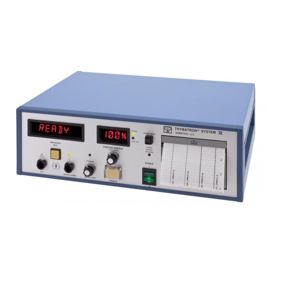
THYMATRON® System IV
SERVICE MANUAL
WARNING:
THE FOLLOWING SERVICING INSTRUCTIONS
ARE FOR USE BY QUALIFIED PERSONNEL
ONLY. TO AVOID PERSONAL INJURY, DO NOT
PERFORM ANY SERVICING UNLESS YOU ARE
QUALIFIED TO DO SO.
Document number: SM-TS4
REV: 3.1
Date: September 15, 2015
Check our website at least once a year for updated User's Manual and Service
Manual. Downloads are available there.
Technical Support, USA and Canada:
Telephone: +1-847-234-6761
E-Mail:
sales@thymatron.com
Please check for revisions and change of information at the rear of this manual
SOMATICS, LLC
+1-800-642-6761
Fax: +1-847-234-6763
Web Site:
www.thymatron.com
1
REV: 3.1 09/15/2015
Advertisement
Table of Contents

Related Manuals for Somatics THYMATRON System IV

Summary of Contents for Somatics THYMATRON System IV
- Page 1 Check our website at least once a year for updated User's Manual and Service Manual. Downloads are available there. Technical Support, USA and Canada: +1-800-642-6761 Telephone: +1-847-234-6761 Fax: +1-847-234-6763 E-Mail: sales@thymatron.com Web Site: www.thymatron.com Please check for revisions and change of information at the rear of this manual SOMATICS, LLC REV: 3.1 09/15/2015...
- Page 2 Copyright © 2015 Somatics, LLC All rights reserved. Contents of this publication may not be reproduced in any form without written permission of Somatics, LLC Products of Somatics, LLC are covered by U.S. and foreign patents and/or pending patents Thymatron®, Thymatron®DG, Thymatron®DGx, Thymatron® System IV DualGraph™, Flexdial, Crona™...
- Page 3 CONTENTS PAGE 1. EXPLANATION OF OPERATING CONTROLS 2. SAFETY CHECK 3. CALIBRATION CHECK 4. THEORY OF OPERATION 5. CALIBRATION AND FACTORY PRESETS 6. SPECIFICATIONS 7. CONNECTOR DEFINITIONS 8. PERCENT ENERGY TABLES 9. SCHEMATICS and ASSEMBLY SOMATICS, LLC REV: 3.1 09/15/2015...
- Page 4 1.1 fig. 1.2 SOMATICS, LLC REV: 3.1 09/15/2015...
- Page 5 The switch must be depressed for the duration of the stimulus. The delivery of the stimulus is indicated by the TREAT button light and a warbling sound. If the button is released, the stimulus will be immediately terminated. SOMATICS, LLC REV: 3.1 09/15/2015...
- Page 6 20% it trips an audio alarm and sets off the LED. It also disables the output. The only way to reset this is to turn off the system. SOMATICS, LLC REV: 3.1 09/15/2015...
- Page 7 To perform this test you must use a dummy load (200 ohms, 10 watts resistor). CAUTION: Never use a two prong power adapter as it is unsafe. SOMATICS, LLC REV: 3.1 09/15/2015...
- Page 8 _________ (<100) Reverse _________ (<100) Reverse _________ (<100) Normal _________ (<100) Leakage to Patient (Sink), use the isolated voltage source in series with the probe. GROUND POWER POLARITY LEAKAGE (µA) Normal _________ (<20) Fig 2.1 SOMATICS, LLC REV: 3.1 09/15/2015...
- Page 9 Connect Oscilloscope across the dummy load. Be sure the scope can measure up to 500 volts. If not, construct a high impedance divider such as in fig. 3.2. optional: if available use 10x probe instead fig. 3.2 CAUTION: HIGH VOLTAGES ARE PRESENT DURING TESTING. EXERCISE CAUTION TO PREVENT INJURY. SOMATICS, LLC REV: 3.1 09/15/2015...
- Page 10 100% and push TREAT button. Observe wave shape as in figure 3.3. Peak voltage reading should be 180 Volts ±7.5% which corresponds to 900 ma at 200 ohms. For other loads wave shapes see fig.3.4 fig 3.3 SOMATICS, LLC REV: 3.1 09/15/2015...
- Page 11 SOMATICS, LLC REV: 3.1 09/15/2015...
- Page 12 Make sure the overshoot does not double trigger the counter. Set PERCENT ENERGY dial to an appropriate setting and press the TREAT button. Note the counter reading and check for correspondence to table 3.1. Repeat procedure for rest of the settings. SOMATICS, LLC REV: 3.1 09/15/2015...
- Page 13 0_ ±100_. Repeat for 1000_ and 2000_. At impedances higher than 3000 _ the display will read >3000 and blink. CAUTION: DO NOT PRESS THE TREAT BUTTON DURING THIS TEST. THE LARGE POWER OUTPUT COULD DESTROY YOUR RESISTANCE BOX. SOMATICS, LLC REV: 3.1 09/15/2015...
- Page 14 THYMATRON®IV on and press TREAT button. Right after the stimulus is delivered a modulated sound should be heard from the speaker. The volume knob on the back may be adjusted. Vary the frequency and amplitude of the oscillator and note the changes in the sound. SOMATICS, LLC REV: 3.1 09/15/2015...
- Page 15 The sound system consists of a 3" speaker and a volume potentiometer mounted on the rear panel. The amplifier sums up the various sources of warning signals as well as the EEG modulated sound. The EEG sound is the only one that can be controlled by the SOMATICS, LLC REV: 3.1 09/15/2015...
- Page 16 It is programmed to be able to run at three speeds: 5mm, 25mm and 50 mm/sec. The 5 V power for the digital circuitry and the 24 V power for the thermal head and the motor are supplied by the power board. SOMATICS, LLC REV: 3.1 09/15/2015...
- Page 17 DIAGNOSTIC CN206 CN201 CN202 CONTROL BOARD CN203 CN205 CN204 SW602 CN302 CN301 PRINTER 115/230V CN303 T102 POWER /OUTPUT SWITCH OUTPUT BOARD T101 CN 304 POWER VOLUME RS232 PR101 CN601 CN602 ALARM SPEAKER SW601 fig 4.1 SOMATICS, LLC REV: 3.1 09/15/2015...
- Page 18 Volts. (It may help to temporarily set the oscillator to 30 Hertz but remember to reset it back down to 10 Hz when finished with adjusting of the volts). Connect all 4 channels to the oscillator according to fig. 3.7. Press the START/STOP button and let the system SOMATICS, LLC REV: 3.1 09/15/2015...
- Page 19 180 volts ± 7.5% peak, adjust VR301 for proper output. See fig. 5.2 POWER SUPPLY VOLTAGE ADJUSTMENT Connect DMM probes between the case of LM338 +5V regulator and ground on the power board. Adjust VR302 to 5.0 Volts. Repeat for +24 V but adjust VR303. See fig. SOMATICS, LLC REV: 3.1 09/15/2015...
- Page 20 Press the Flexdial button again and CONFIG will be displayed. All the configuration settings are stores in the battery backed memory and will remain there even with the power switched off. SOMATICS, LLC REV: 3.1 09/15/2015...
- Page 21 CMRR 80 dB Printer Resolution 200 dots/inch Adjustments Position, Gain on each channel (use Flexdial) Channels 1 -4 selectable Time/Date Battery backed DIMENSIONS Width 18 inches Depth 13 inches Height 5.25 inches Weight 22 lbs. SOMATICS, LLC REV: 3.1 09/15/2015...
- Page 22 CN106- 3pin SIP OUTAO OUTBO CN105- 3pin SIP OUTAI OUTBI CN101- 10pin SIP +speaker -speaker volume-high volume-center volume-low CN102- 40 pin DIN warn sound To Control EEG sound enable [EEGS] -ALARM GAIN -EADC -RST -ADERR SOMATICS, LLC REV: 3.1 09/15/2015...
- Page 23 -ADEF -ADDR -ADTR ENERGY0 ENERGY1 ENERGY2 ENERGY3 ENERGY4 2xEN -TREATSW 2. CONTROL BOARD CN201- 40 pin DIN warn sound To Analog EEG sound enable [EEGS] -ALARM GAIN -EADC -RST -ADERR -ADEF -ADDR -ADTR ENERGY0 ENERGY1 SOMATICS, LLC REV: 3.1 09/15/2015...
- Page 24 ENERGY2 ENERGY3 ENERGY4 2xEN -TREATSW CN202- 40pin DIN warn sound To Display MENULED GAIN -EAND -RST ENERGY0 ENERGY1 ENERGY2 ENERGY3 ENERGY4 2xEN FLEX0 FLEX1 FLEX2 FLEX3 -RLTREAT TRIND PLED SOMATICS, LLC REV: 3.1 09/15/2015...
- Page 25 CN203- 50pin HDDIN -PRRD To Printer -PRWR BUSY SOMATICS, LLC REV: 3.1 09/15/2015...
- Page 26 -RST ERROR -FEED -SOUT -SIN INTRP POST BRDY +SUP ABUFF -SUP CN204- 10 pin DIN To RS232 SOMATICS, LLC REV: 3.1 09/15/2015...
- Page 27 3 POWER/OUTPUT BOARD CN301 12pin SIP To Control OUTA OUTB CN302 6pin SIP PGND To Printer PGND +24V +24V LGND CN303- 5pin SIP T305 T304 CN304- 10pin SIP 5Vac-A 5Vac-A 5Vac-B 5Vac-B +24Vac +24Vac -24Vac SOMATICS, LLC REV: 3.1 09/15/2015...
- Page 28 24V CT 24V CT 4. DISPLAY BOARD CN401- 40pin DIN warn sound To Control MENULED GAIN -EAND -RST ENERGY0 ENERGY1 ENERGY2 ENERGY3 ENERGY4 2xEN FLEX0 FLEX1 FLEX2 FLEX3 -TREATSW TRIND PLED CN402- 5 pin SIP -TREATSW SOMATICS, LLC REV: 3.1 09/15/2015...
- Page 29 ENOUTB ENOUTA CN405- 6 pin SIP SETSW ADOUTB ADOUTA CN407- 3 pin SIP -ALARMSW 5 FRONT PANEL CN501- 9pin Hyperion +ch1 -ch1 +ch2 -ch2 +ch3 -ch3 +ch4 -ch4 isognd CN502- 7pin Hyperion OUTAO OUTBO RTREATA SOMATICS, LLC REV: 3.1 09/15/2015...
- Page 30 Start/Stop switch -STSTSW SW505- Energy switch ENERGYSW ENOUTB ENOUTA SW506- Adjust/Set switch SETSW ADOUTB ADOUTA SW507 Power switch LINE NEUTRAL SWLINE SWNEUTRAL 6 REAR PANEL CN601- 9pin DB RS232 CN602 3pin IEC line Power neutral SOMATICS, LLC REV: 3.1 09/15/2015...
- Page 31 SW602 115/230 Voltage switch SW601- Alarm test -ALARMSW SOMATICS, LLC REV: 3.1 09/15/2015...
- Page 32 PERCENT ENERGY TABLES Frequency Chart (Hz) for Thymatron System IV Percent DGx Lowest Low .25 Low .5 Energy Pulse width (ms) for Thymatron System IV---US version Percent DGx Lowest Low .25 Low .5 Energy Charge Charge Charge Charge 0.25 0.25 0.25...
- Page 33 0.25 0.25 0.25 0.25 0.25 0.25 2X Energy (Not available in the US) Percent Pulsewidth Frequency Energy 0.75 0.75 0.75 0.75 0.75 SOMATICS, LLC REV: 3.1 09/15/2015...
Need help?
Do you have a question about the THYMATRON System IV and is the answer not in the manual?
Questions and answers