Table of Contents
Advertisement
Quick Links
Advertisement
Table of Contents

Subscribe to Our Youtube Channel
Related Manuals for SMC Networks IL100

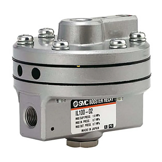
Summary of Contents for SMC Networks IL100
- Page 1 No.IL01-OM00006-B PRODUCT NAME BOOSTER RELAY MODEL/ Series IL100...
-
Page 2: Table Of Contents
Table of Contents Instructions for your Safety 1~2 1. Outline 2. Specification 3. Structure and the Operation Principle 3~4 4. Transportation and Storage 5. Precautions in Using 6. Maintenance 7~8 7. Countermeasures for Failure 8. Spare Parts List 9. Drawing... - Page 3 Safety Instructions These safety instructions are intended to prevent hazardous situations and/or equipment damage. These instructions indicate the level of potential hazard with the labels of “Caution,” “Warning” or “Danger.” They are all important notes for safety and must be followed in addition to International Standards (ISO/IEC) , and other safety regulations.
- Page 4 Safety Instructions Caution The product is provided for use in manufacturing industries. The product herein described is basically provided for peaceful use in manufacturing industries. If considering using the product in other industries, consult SMC beforehand and exchange specifications or a contract if necessary. If anything is unclear, contact your nearest sales branch.
-
Page 5: Outline
1. Outline Increase the operating speed of controlling part when the piping between the instruments and the controlling part is very long, or the controlling part capacity is large. 2. Specification Supply pressure MAX.1.0MPa Input・Output pressure MAX.0.7MPa Output flow More than 600l/min(ANR)(SUP.0.5MPa) Air consumption Less than 3l/min(ANR) (OUT.0.5MPa) Within ±1%... - Page 6 MODEL IL100 BOOSTER RELAY ADJUSTABLE NEEDLE VALVE DIAPHRAGM(A) INPUT CHAMBER DIAPHRAGM(B) EXHAST HOLE INTERNAL VALVE NEEDLE VALVE PRESSURE DISPLACEMENT FORCE PRESSURE DIAPHRAGM(A) MAIN VALVE ― ㎡ EQUIVALENT SPRING Pa/M FORCE DIAPHRAGM(B) ㎡ MODEL IL100 BLOCK DIAGRAM...
-
Page 7: Transportation And Storage
4. Transportation and Storage Warning (1) Handle the product with care. (2) Do not expose to rain. (3) The product is packed in a vinyl bag for shipment to prevent from dust. Avoid taking out of the bag just before piping even after unpacking. (4) If the product is kept unpacking for a certain period, select a place where there is no moisture nor corrosive gas. -
Page 8: Precautions In Using
5. Precautions in using Warning Operation (1) Do not operate the booster relay out of the specifications, because it causes malfunction. (2) If booster relay failure affecting the system is expected, provide a safety circuit for the system to avoid danger. Warning Handling (1) Excess vibration and impact on the booster relay cause failure, may cause failure, so that... -
Page 9: Maintenance 7~8
6. Maintenance Warning (1) To handle compressed air, person that has experienced and has knowledge about instrumentation machine is suitable. That kind of person should operate unit replacement and maintenance with keeping product specification. (2) To remove booster relay or to replace unit with product set, please exhaust residual pressure within piping with supply air stopped. - Page 10 Warning (Adjustment on Part replacement) Diaphragm replacement and product disassemble & re-assemble may change in/output characteristics. For that circumstances, adjust main valve length. Main valve, as shown below, is adjusted the length by screw and fixed with lock nut. To adjust length, loose lock nut. For the main valve length adjustment, make longer when output is low to input signal.
-
Page 11: Countermeasures For Failure
7.Countermeasures for failure Warning Avoid use when failure is not solved. Phenomenon Cause Countermeasures Dust attach supply port or Disassemble and clean. Too much flow from exaust exaust port (If flawed, replace the part.) port Broken diaphragm Replace diaphragm Pressure leak due to loosen Tighten screw screw No signal even if input... -
Page 12: Spare Parts List
Spare parts list Page 1/1 Doc.No. IL01-SL00008 Model Name IL100・Spare parts list KT-IL100 Model No. Description Sketch Material Pcs. Drawing Symbol Drawing No. Using Spare 26100-1 A2017 261017 A2017 261015 Diaphragm A2017 261014 Ass’y 261012 A2017 261010 φ86 A2017 26108 RESINIUM 26109 Spring... - Page 13 No.IL01-OM00006-B -11-...
- Page 14 No.IL01-OM00006-B A Safety instructions update B Drawing update 4-14-1, Sotokanda, Chiyoda-ku, Tokyo 101-0021 JAPAN Tel: + 81 3 5207 8249 Fax: +81 3 5298 5362 http://www.smcworld.com Note: Specifications are subject to change without prior notice and any obligation on the part of the manufacturer. ©...
Need help?
Do you have a question about the IL100 and is the answer not in the manual?
Questions and answers