
Summary of Contents for Bentek Solar BTK6-MDSS Series
- Page 1 Multiple Disconnect Safety System Installation and Operating Instructions Important Safety Instructions Save These Instructions...
- Page 2 © 2011-2012, 2014 Bentek, Inc. All rights reserved. No part of this publication (hardcopy or electronic form) may be reproduced or transmitted, in any form or by any means, electronic, mechanical, photocopying, recording, or otherwise, without the prior written consent of Bentek. All trademarks are owned by their respective owners.
-
Page 3: Table Of Contents
Table of Contents About This Book Intended Audience ........... . 5 Notation Conventions . - Page 4 Contents Multiple Disconnect Safety System Installation and Operating Instructions 950-001568-000 Rev A...
-
Page 5: About This Book
About This Book This manual provides information on installing the Bentek Multiple Disconnect Safety System. Information is included on mounting the equipment on a prepared base and connecting the wires to the proper locations. Intended Audience This manual is for those qualified to deal with the dangers and hazards involved in installing electric devices. -
Page 6: Manual Organization
About This Book Manual Organization This manual is organized as follows: Chapter 1, “Safety Instructions,” provides information on warnings and guidelines for installing the product safely. Chapter 2, “Product Description,” describes the MDSS and provides specifications. Chapter 3, “Installation Procedure,” describes how to install the MDSS. -
Page 7: Chapter 1: Safety Instructions
Chapter 1 Safety Instructions This manual contains important safety instructions for the following Bentek MDSS equipment: Model # BTK6-MDSS-xxyyy Model # BTK6-MDSS-xxyyy-DF Model # BTK10-MDSS-xxyyy Model # BTK10-MDSS-xxyyy-DF NOTE In model numbers, xx refers to the number of switches and yyy refers to the switch rating while DF refers to Dead Front. -
Page 8: Information For Technicians
Chapter 1: Safety Instructions WARNING Inputs from the field panel and outputs to the inverter may be hot! Do not touch components or parts associated with these connection points. Severe burns or death can occur. Install the MDSS enclosure so that it conforms to national and local safety ... -
Page 9: Chapter 2: Product Description
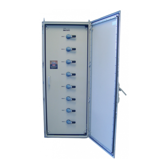
Chapter 2 Product Description Bentek Solar Multiple Disconnect Safety System (MDSS) is designed for large PV solar systems (250KW or greater) and is intended for installation next to the inverter. It is comprised of multiple UL 600VDC or 1000VDC load-break disconnects contained in one easy-to-install compact enclosure. - Page 10 Chapter 2: Product Description Figure 1 MDSS (front views) With nine dual-column disconnects— With eight single-column disconnects— handles installed on front door handles installed on dead front (handles in off position) (handles in off position) Multiple Disconnect Safety System Installation and Operating Instructions 950-001568-000 Rev A...
-
Page 11: Specifications
Chapter 2: Product Description Specifications Table 1 through Table 4 show the specifications for MDSS models. NOTE In model numbers, xx refers to the number of switches and yyy refers to the switch rating while DF refers to Dead Front. Table 1 Electrical Specifications of MDSS Installed Internal... -
Page 12: Components
Chapter 2: Product Description Components The MDSS is a prewired, floor-mounted NEMA-3R electrical enclosure that contains the following components: Disconnects—600VDC or 1000VDC interrupt switches. Plastic Shields or Phase Barriers—Guards that increase safety by preventing unintentional contact with live parts. Extended Terminal (optional)—Extension to the input and output terminals. - Page 13 Chapter 2: Product Description Figure 2 MDSS with four double-stack 1000V/400A disconnects - inside front view Output #1 (upper) Input #1 (upper) Output #2 Input #2 (lower) (lower) Double-stack disconnect units, each containing an upper and a lower unit Output #7 Input #7 (upper) (upper)
- Page 14 Chapter 2: Product Description Figure 3 MDSS with 10 dual-column 1000V/250A disconnect units - inside front view Input #1 Input #2 Output #1 Output #2 Input #9 Input #10 Output #9 Output #10 Multiple Disconnect Safety System Installation and Operating Instructions 950-001568-000 Rev A...
- Page 15 Chapter 2: Product Description Figure 4 MDSS with 8 single-column 600V/100A disconnect units - inside front view Input #1 Output #1 Input #8 Output #8 Multiple Disconnect Safety System Installation and Operating Instructions 950-001568-000 Rev A...
-
Page 16: Explanation Of Symbols Used On Equipment
Chapter 2: Product Description Explanation of Symbols Used on Equipment The following symbols are used to identify parts and provide warnings for the MDSS. Table 5 Symbols on Equipment ELECTRICAL SHOCK HAZARD—This symbol indicates the presence of electric shock hazards. Enclosures marked with these symbols should only be opened by an authorized service provider. -
Page 17: Chapter 3: Installation Procedure
Chapter 3 Installation Procedure This chapter describes the mounting and wiring or connections required to install the MDSS. Prior to mounting and wiring the MDSS, remove any shipping supports or materials. Contact Bentek Support at 1-888-202-5009 for additional assistance. Required Tools and Materials Standard construction, electrical tools, and basic electrical safety and testing instruments are required for the installation of the MDSS enclosure. -
Page 18: Preparing To Install The Mdss
Chapter 3: Installation Procedure Preparing to Install the MDSS Refer to the project drawings to identify the mounting location and any specific location requirements or special instructions. The MDSS must be mounted in a position and at a location where the door is easily accessible. Figure 5 Diagram of the required door swing The mounting base must be at least as large as the enclosure to be mounted and be able to support the weight of the equipment. -
Page 19: Opening And Closing The Enclosure Door
Chapter 3: Installation Procedure Opening and Closing the Enclosure Door Up to ten disconnect handles (depending on the model) are located on the front of the enclosure or on the optional dead front. When the handles are on the door, each of these handles (Figure 6) must be in the Off position to allow the door to open. -
Page 20: Opening The Dead Front
Chapter 3: Installation Procedure The handle of the enclosure door (Figure 7) has a tool-activated lock at the bottom. Unlock with a flat-head screw driver. This releases the door handle. Lift the bottom of the handle to release the latch and open the door. The door handle also has an 3/8-inch eyelet to accommodate a padlock. -
Page 21: Mounting The Mdss
Chapter 3: Installation Procedure Mounting the MDSS Your mounting base may have been prepared with studs or you have the option to drill into the base and use lags and lag screws to install the floor-mount enclosure. Brackets with predrilled holes are located in the four corners of the bottom skin. - Page 22 Chapter 3: Installation Procedure Figure 9 shows the bottom of the enclosure for double-stacked and dual-column models. The gland plates have been removed. The recommended opening for cables is through the bottom with one or more of the gland plates removed. Figure 9 Bottom view of the enclosure for double-stacked and dual-column models, showing panels removed The single-column model has a 1-5/8 x 13/16-inch strut across the bottom.
- Page 23 Chapter 3: Installation Procedure Figure 10 Bottom view of the enclosure for 100A-250A single-column models with dead front, showing panels removed Strut Dead front Predrilled Additional Bracket (4) hole (4) holes (12) Figure 11 Bottom view of the enclosure for 100A-250A single-column models without dead front, showing panels removed Strut Predrilled...
- Page 24 Chapter 3: Installation Procedure Figure 12 Bottom view of the enclosure for 400A single-column models with dead front, showing panels removed Strut Dead front Predrilled Additional Bracket (4) hole (4) holes (12) Figure 13 Bottom view of the enclosure for 400A single-column models without dead front, showing panels removed Strut Predrilled...
-
Page 25: Preparing The Cutouts
Chapter 3: Installation Procedure Close and fasten the door prior to positioning the enclosure. Use a crane to move the enclosure into position. Secure the appropriate screws or connectors to attach the enclosure to the base. CAUTION CAUTION The MDSS may be unstable when being moved. Use of the eyebolts when moving the enclosure is recommended. - Page 26 Chapter 3: Installation Procedure CAUTION CAUTION Apply a rust inhibitor and touch-up paint after making cutouts. Be sure to clean up any spatter immediately. If it is not cleaned up, it may cause rust in the enclosure. If rusting occurs, use a rust remover and then apply touch-up paint to prevent further rusting.
- Page 27 Chapter 3: Installation Procedure Figure 15 Positions for cutouts in the sides and back of the enclosure for dual-column MDSS Side Back Multiple Disconnect Safety System Installation and Operating Instructions 950-001568-000 Rev A...
- Page 28 Chapter 3: Installation Procedure Figure 16 Position for cutouts in the sides and back of the single-column MDSS Side Back CAUTION CAUTION Follow installation instructions from the fittings manufacturer to assure water-tight connections on all areas of the enclosure. Improper fittings may void the warranty. Multiple Disconnect Safety System Installation and Operating Instructions 950-001568-000 Rev A...
-
Page 29: Connecting Wires
Chapter 3: Installation Procedure Connecting Wires NOTE Unless otherwise specified, wiring methods must be in accordance with the National Electrical Code, ANSI/NFPA 70. 1. Prior to connecting the wires, remove the plastic shield protecting the connectors. 1. Use the wiring guidelines from the torque label for proper wiring selection. The torque label is located on the inside of the dead front or the inside of the front door. - Page 30 Chapter 3: Installation Procedure Figure 18 Example of connecting wires coming through the bottom of a double-stack MDSS containing eight 1000V/250A disconnects and four handles Input #1 (upper) Input #1 (upper) Output #1 Input #2 (lower) Input #2 (lower) Output #2 disconnect handle on dead font...
- Page 31 Chapter 3: Installation Procedure Figure 19 Example of connecting wires coming through the bottom of a dual-column MDSS with ten 1000V/250A disconnects Disconnect handle on door Input #2 Input #1 Front view Left side view Ground busbar Multiple Disconnect Safety System Installation and Operating Instructions 950-001568-000 Rev A...
- Page 32 Chapter 3: Installation Procedure When the dual-column MDSS has the disconnect handles mounted on a dead front instead of on the front door, the disconnect units are moved toward the back of the enclosure. Figure 20 shows the left side view of the wiring diagram and the position of the disconnect units.
- Page 33 Chapter 3: Installation Procedure Figure 21 Example of connecting wires coming through the bottom of a single-column MDSS with eight 600V/100A disconnects; disconnect handles are mounted on the dead front Disconnect handles on dead front Input #1 Output #1 Left side view Front view Ground busbar Multiple Disconnect Safety System Installation and Operating Instructions...
-
Page 34: Connecting Conductors From Source Circuits
Chapter 3: Installation Procedure Connecting Conductors from Source Circuits Verify that the inverter is off. Source circuits refer to output from PV arrays through the combiner and optionally the recombiner to the MDSS. 1. Label each wire from the source circuit with a reference number and its polarity. -
Page 35: Attaching Conductors From The Inverter
Chapter 3: Installation Procedure Attaching Conductors From The Inverter After referring to the electrical drawings to determine which wire to use, connect ungrounded wires and ground conductors to appropriate points in the inverter. 1. Install the conduit if a cutout is being used. 2. -
Page 36: Preventative Maintenance
Chapter 3: Installation Procedure Preventative Maintenance Contact Bentek Support at 1-888-202-5009 for assistance. The MDSS should be inspected at regular intervals; semi-annually is recommended. CAUTION CAUTION Refer servicing to qualified personnel. Maintain the torque settings as listed on the torque label (inside the dead ...
Need help?
Do you have a question about the BTK6-MDSS Series and is the answer not in the manual?
Questions and answers