Table of Contents
Advertisement
Quick Links
Advertisement
Table of Contents

Subscribe to Our Youtube Channel
Related Manuals for NPI TC-10

Summary of Contents for NPI TC-10
- Page 1 OPERATING INSTRUCTIONS AND SYSTEM DESCRIPTION FOR THE TC-10 TEMPERATURE CONTROL SYSTEM VERSION 3.9 npi 2018 npi electronic GmbH, Bauhofring 16, D-71732 Tamm, Germany Phone +49 (0)7141-9730230; Fax: +49 (0)7141-9730240 support@npielectronic.com; http://www.npielectronic.com...
-
Page 2: Table Of Contents
TC-10 User Manual ________________________________________________________________________________________________________________ Table of Contents Safety Regulations ......................3 TC-10 Components ......................4 TC-10 System ........................4 3.1. System Description ...................... 4 3.2. Description of the Front Panel ..................5 ... -
Page 3: Safety Regulations
(e.g. for diagnosis or treatment of humans), or for any other life-supporting system. npi electronic disclaims any warranties for such purpose. Equipment supplied by npi electronic must be operated only by selected, trained and adequately instructed personnel. -
Page 4: Components
The TC-10 temperature control system is designed for heating purposes in electrophysiological experiments. The TC-10 system is housed in a 19 inch standard cabinet, with a built-in power supply and cooling elements for the power devices. The TC-10 guarantees low noise operation and has special protection features to prevent the preparation from damage. -
Page 5: Description Of The Front Panel
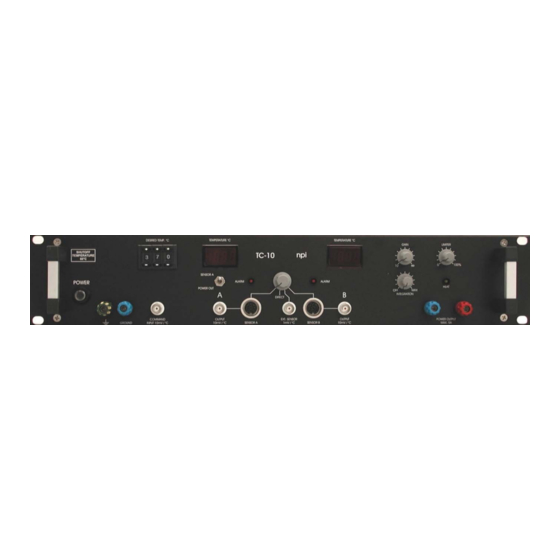
TC-10 User Manual ________________________________________________________________________________________________________________ 3.2. Description of the Front Panel Figure 1: TC-10 front panel view ___________________________________________________________________________ version 3.9 page 5... - Page 6 TC-10 User Manual ________________________________________________________________________________________________________________ In the following description of the front panel elements each element has a number that is related to that in Figure 1. The number is followed by the name (in uppercase letters) written on the front panel and the type of the element (in lowercase letters). Then, a short description of the element is given.
- Page 7 TC-10 User Manual ________________________________________________________________________________________________________________ (6) TEMPERATURE °C B display Digital display to indicate the temperature determined by SENSOR B (16). (7) ALARM LED LED to indicate that temperature SENSOR B (16) is not connected, broken or short-circuited. The POWER OUTPUT (18 / 19) shuts down if this LED is on and the MODE switch (14) is set to SENSOR B.
- Page 8 (max. 12V DC and 5A) for devices with the DIN connector cable assembly. (e.g. HPC-G, see www.alascience.com). (14) MODE switch Switch to select the operation modes of the TC-10. Four modes are available: SENSOR A: the temperature determined by SENSOR...
- Page 9 TC-10 User Manual ________________________________________________________________________________________________________________ (16) SENSOR B connector 8-pole connector for temperature SENSOR B. This connector also provides the POWER OUTPUT (18 / 19) for the heating unit (max. 12V DC and 2.5A) for devices with the DIN connector cable assembly. (e.g.
-
Page 10: Rear Panel Elements
TC-10 User Manual ________________________________________________________________________________________________________________ 3.3. Rear Panel Elements LINE VOLTAGE SELECTION: The selector for the line voltage and the connector for the power cord are located in a mains connection module on the rear panel of the instrument. If operated with other line voltage the instrument may be damaged if the wrong line... -
Page 11: Modes Of Operation
0 V to 12 V. The ALARM circuit (see below) is disabled in this mode. The TC-10 is designed with an unipolar output (0-12 Volt DC). If a resistive load is used, the system can be used for heating purposes in all modes (SENSOR and DIRECT). -
Page 12: Setting The Desired Temperature
1. The easiest way is to use the digital potentiometer DESIRED TEMP. / °C. The temperature can be set from +03.0 °C to +60.0 °C, resolution: 0.1 °C. If the TC-10 leaves this temperature window the internal shut-off unit disconnects the power output. -
Page 13: Temperature Sensors / Block Diagram
TC-10 User Manual ________________________________________________________________________________________________________________ 5. Temperature sensors / Block diagram 5.1. DIN Connector Figure 2: How to connect the temperature sensor ___________________________________________________________________________ version 3.9 page 13... -
Page 14: Available Sensors
TC-10 User Manual ________________________________________________________________________________________________________________ Figure 3: Connector pinout of the DIN connector (pins 1 and 3 are connected internally) 5.1. Available sensors Figure 4: Temperature sensors and cable. The sensors come with a connection cable (TS-CAB, see Figure 4, left) with a DIN connector on one end and two 1 mm connectors on the other end. -
Page 15: Block Diagram
TC-10 User Manual ________________________________________________________________________________________________________________ 5.2. Block diagram Figure 5: Block diagram of the TC-10 ___________________________________________________________________________ version 3.9 page 15... -
Page 16: Operating Guide - Tuning Procedure
SENSOR are using the same channel. Otherwise the heating device may be damaged due to overheating. In the following it is assumed that you use heating devices delivered by npi or ALA Scientific Instr. with 12V operating voltage. Please follow these instructions step by step to avoid problems in adjusting the instrument. - Page 17 As mentioned above it is very important that the sensor element and the heating element are in good thermal connection. In Figure 6 the time course of temperature regulation of the TC-10 is shown. As resistive load a bulb (12V, 21W) was used. The temperature sensor was fixed directly on the bulb and sensor and bulb were wrapped with foam.
-
Page 18: Operation With Hpt-2A Heated Perfusion Tube (Discontinued)
TC-10 User Manual ________________________________________________________________________________________________________________ 6.1. Operation with HPT-2A Heated Perfusion Tube (discontinued) For use with HPT-2A from ALA please follow these hints. Always use the LIMITER. Do not set the LIMITER to more than 50% for a longer time, since the HPT-2A will melt if operated at more than 5V. -
Page 19: Technical Data
TC-10 User Manual ________________________________________________________________________________________________________________ 8. Technical Data for semiconductor 2252 at 25 °C (standard) or platinum Sensor input: 100 at 0 °C, accuracy typically 0.1 °C at 25 °C, with electronic protection Sensor input (EXT. Mode): 1 mV / °C...
Need help?
Do you have a question about the TC-10 and is the answer not in the manual?
Questions and answers