
Related Manuals for Unifire FORCE 80


Summary of Contents for Unifire FORCE 80
- Page 1 FORCE 80 BLCD with TARGA Robotic Nozzle PLC Generic system manual FORCE50 BLDC and the TARGA Robotic Nozzle PLC rev 1511 page 1(24)
- Page 2 This professional equipment should only be used by qualified and trained professionals who have read and understood this manual. So please read this manual before installing and operating your new FORCE 80. It will familiarize you with the dangers associated with operation, as well as provide proper installation and operation instructions.
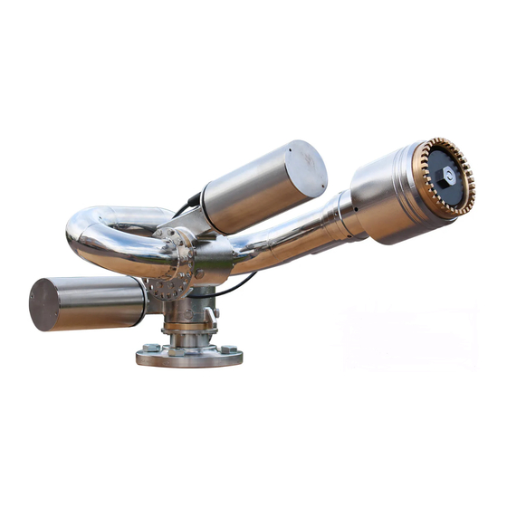
- Page 3 TECHNICAL SPECIFICATIONS FORCE 80 BLDC The UNIFIRE FORCE 80 is a marine specification, stainless steel foam and water robotic nozzle. The finish is manually polished stainless steel, providing a long service life of fantastic look with minimum maintenance. It features M12 multi-connectors on all connection points for simple installation and maintenance.
-
Page 4: Table Of Contents
General Information & Warnings Spare parts specification Joystick “PI” Adjusting the flow of INTEG80 Flow chart of the FORCE 80 with INTEG 80 Reach chart of FORCE 80 with INTEG80 Operating the Joystick MAINTENANCE of the FORCE 80 with BLDC motors MAINTENANCE of the INTEG 80 with BLDC motors Canbus JOYSTICK Description &... - Page 5 Unifire or download it at www.unifire.com. If you have any questions relating to this equipment and its safe use please contact Unifire prior to use at +46 303 248 400. DO NOT ATTEMPT TO MODIFY THIS EQUIPMENT IN ANY WAY.
- Page 6 80 robotic nozzle is capable of withstanding a nozzle reaction force of at least twenty thousand (20,000) Newtons (2000 kgf). The FORCE 80 robotic nozzle should not be used on a portable stand of any kind, as such use can be extremely dangerous and can result in Serious Injury or Death.
- Page 7 KEEP A SAFE DISTANCE DURING OPERATION AND MOVEMENT. The FORCE 80 robotic nozzle has moving parts. Be sure to keep a safe distance from the robotic nozzle as it moves and keep hands and fingers away from pinch points to avoid injury.
- Page 8 ONLY USE THE MANUAL OVERRIDE IN CASE OF TRUE EMERGENCY & POWER FAILURE. The manual override controls on the FORCE 80 are not designed for normal operation and should only be used in the case of extreme emergency and when the remote control feature is not working sufficiently to control the robotic nozzle by means of the electronic controls.
-
Page 9: Installation Force 80 Chassis
SECURED AT ALL TIMES DURING OPERATION! Serious injury or death can occur if the robotic nozzle is not fully and properly secured and supported. Be sure that the mounting pipe for the FORCE 80 is capable of withstanding a nozzle reaction force of at least eight thousand (20,000) Newtons (2000 kgf). -
Page 10: Spare Parts Specification
Spare parts specification ITEM NAME & IMAGE PART # BRIEF DESCRIPTION Complete FORCE 80 FORCE 80BLDC Unifire FORCE 80 Robotic Nozzle with Robotic nozzle BLDC motor. M12 multi-connectors, or cable-gland connection. COMPLETE GEAR FOR80200 Complete worm gear assembly with ASSEMBLY gear wheel, gear screw, bearings, o- ring. - Page 11 ITEM NAME & IMAGE PART # BRIEF DESCRIPTION Middle pipe section FORCE 80-PS1 Flange connection with 10 x (M5x16) at both ends Complete BLDC motor with 3910103 BLDC 24:1 welded cover 3910107 BLDC 49:1 3910108 BLDC 84:1 Control circuit board TARGA_BASE Robotic Nozzle PLC Motherbard.
- Page 12 ITEM NAME & IMAGE PART # BRIEF DESCRIPTION JOYSTICK PI FOR00207 or Joystick PI, progressive joystick control, FOR00209 including LED position indicator lights, record/play, 2 x auxiliary. Weight: 1 Kg M12 5-pin connector TARGA PLC TARGA1….6 TARGA Robotic PLC with up to 6 x BLDC driver.
-
Page 13: Joystick "Pi
Joystick “PI” The following is an overview of the Unifire “PI” Joystick functions. For full operation instructions, see the Operation Instruction section. For full technical specification and setup of the Joystick see Appendix 2 ON button for Joystick control activation... - Page 14 FLOW ADJUSTMENT of INTEG 80 The flow is set by adjusting the opening slot ”B”. (outlet area) This is done by rotating the baffle ”A” that rides on a threaded rod, M16 x 2. 1. Rotate the baffle ”A” clockwise until it stops. Now the slot ”B” is closed. (pos=0) 2.
- Page 15 FORCE 80 FLOW & REACH CHARATERISTICS The future of firefighting UNIFIRE FORCE 80 (v.1.2012) page 1...
- Page 16 Flow chart with INTEG 80 nozzle FLOW FORCE 80 with INTEG 80 nozzle LIT/MIN 5500 5250 Results may vary depending upon conditions and the figures should be considered as an 5000 approximate guideline only 4750 3,5 turns 4500 3,0 turns...
- Page 17 Reach chart with INTEG 80 nozzle REACH FORCE 80 with INTEG 80 nozzle Meters effective reach at 35° elevation angle Results may vary depending upon conditions and the figures should be considered as an approximate guideline only 3,5 turns 3,0 turns...
-
Page 18: Operating The Joystick
Operating the Joystick CALIBRATION Operating range setup / Calibration of the TARGA BLDC motor system is done directly on the TARGA setup-panel. Calibration MUST be done prior to operating the Joysticks. Ref to TRAGA PLC section of this manual. START To activate the Joystick, press the ON button. - Page 19 AUX 1 and AUX 2 (generic buttons) These are generic buttons that can control “other functions”. For example, foam valves or flood lights. In a networked system the AUX1 and AUX2 can be used for controlling and switching between 2 robotic nozzles. MANUAL OPERATION WITH CRANKS The robotic nozzle can be manually operated with cranks.
-
Page 20: Maintenance Of The Force 80 With Bldc Motors
The worm gears must normally never be greased. We recommend not ever greasing the gears unless specifically recommended to do so by Unifire AB on an individual, case-by- case basis. If Unifire recommends greasing, then be sure to follow Unifire’s instructions, including by using the proper type of grease (Mobilith SHC460) and make sure to open the grease evacuation plug. -
Page 21: Maintenance Of The Integ 80 With Bldc Motors
We recommend that the stream-shaper get a few drops WD40 every month as a precaution. The nozzle should not be disassembled by the end-user. If damaged, it must be sent to Unifire for repair, or be replaced. rev 1511 page 20(24) -
Page 22: Canbus Joystick Description & Advanced Setup
WARNING!!! This section is for technicians and qualified users. Do not attempt to change the setup of the Joystick unless you are qualified and authorized by Unifire to do so. WARNING! Wrong settings WILL interrupt communication between the Joystick and the PLC. The system will stop working!!! The Joystick provides position feedback in 9 steps. -
Page 23: Setting Baud Rate, Master-Slave Mode And Canbus Id
Setting baud rate, Master-slave mode and Canbus ID For technicians trained and authorized by Unifire only There are two setup modes on the PI Joystick: Setup A and Setup B Setup mode ”A” is used to control the following functions:... -
Page 24: Setup Mode "A
Setup mode “A” PARK VALVE AUX 1 Enter SETUP MODE A AUX 2 PLAY While powering up the joystick press “REC” and “PLAY” until the powered by corresponding LED's are ON. (Power up either by connecting a live Joystick cable, or switching on power) This puts the Joystick in setup mode. Master/slave mode (I, II) The position LED's indicates the mode and address when in setup mode: To switch between master and... -
Page 25: Setup Mode "B
Setup mode ”B” VALVE PARK AUX 1 Enter SETUP MODE B AUX 2 PLAY While powering up the joystick press “VALVE” and “PLAY” until the powered by corresponding LED's are ON. This puts the Joystick in setup mode ”B” 125kbps or 250kbps CAN bus Press VALVE to switch between 125kbps and 250kbps (indicated with full horizontal bar).
Need help?
Do you have a question about the FORCE 80 and is the answer not in the manual?
Questions and answers