Table of Contents
Advertisement
Quick Links
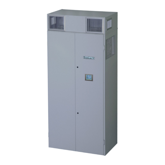
Scholar V Classroom Units: 2 to 5 Ton Cooling Capacity
Models VAIVA36 (14-42 BTUH) VIAVA60 (24-60 BTUH)
with Variable Refrigerant Flow Compressors
WARNING - SAFETY REQUIREMENTS
• If the information in these instructions is not
followed exactly, a fire may result causing
property damage, personal injury or loss of
life.
• Read all instructions carefully prior to
beginning the installation. Do not begin
installation if you do not understand any of
the instructions.
• Improper installation, adjustment, alteration,
service or maintenance can cause property
damage, personal injury or loss of life.
• Installation and service must be performed
by a qualified installer or service agency in
accordance with these instructions and in
compliance with all codes and requirements
of authorities having jurisdiction.
• Follow all safety codes.
E-mail: marvairtech@airxcel.com • Internet: www.marvair.com
The most current version of this manual can be found at www.marvair.com.
Manufactured By:
Marvair
Division of AIRXCEL
®
P.O. Box 400 • Cordele, Georgia 31010
156 Seedling Drive • Cordele, Georgia 31015
(229) 273-3636 • Fax (229) 273-5154
Marvair Scholar V Installation & Startup Manual 07/2016 New
INSTALLATION & STARTUP MANUAL
Scholar V with Free Blow Plenum
, Inc.
™
Part #03079
Advertisement
Table of Contents

Subscribe to Our Youtube Channel
Related Manuals for Airxcel Marvair Scholar V

Summary of Contents for Airxcel Marvair Scholar V
- Page 1 156 Seedling Drive • Cordele, Georgia 31015 (229) 273-3636 • Fax (229) 273-5154 E-mail: marvairtech@airxcel.com • Internet: www.marvair.com The most current version of this manual can be found at www.marvair.com. Marvair Scholar V Installation & Startup Manual 07/2016 New Part #03079...
- Page 2 Used to point out helpful suggestions that will result in improved installation, reliability or IMPORTANT operation. Specifications subject to change without notice. © 7/2016 Marvair , Division of AIRXCEL , Inc. ® ™ Scholar V Installation & Startup Manual 07/2016 New...
-
Page 3: Table Of Contents
HEATING, VENTILATING AND AIR CONDITIONING EQUIPMENT INSTALLATION AND START-UP INSTRUCTIONS FOR SCHOLAR V HEAT PUMP AND AIR CONDITIONER MODEL VAIVA TABLE OF CONTENTS Article Description Page 1.01 Tools/Field Furnished Supplies ............4 1.02 Inspection/Unpacking/Handling............4 1.03 Standard Controls ................7 1.04 Thermostat ..................8 1.05 Optional Controls .................13 1.06... -
Page 4: Tools/Field Furnished Supplies
1.01 TOOLS/FIELD FURNISHED SUPPLIES WARNING TO AVOID PERSONAL INJURY, ADEQUATE PROTECTIVE CLOTHING MUST BE WORN AND PRECAUTIONS IN HANDLING AND INSTALLING THIS EQUIPMENT MUST BE PRACTICED AT ALL TIMES. • Power Drill/Driver & Extension • T25 TORX Bits • 5/16 hex bit •... - Page 5 WARNING DO NOT STACK THE UNIT OR ANY ACCESSORIES ON TOP OF ONE ANOTHER. THE UNITS SHOULD ALWAYS REMAIN IN THE UPRIGHT POSITION WHEN BEING SHIPPED, STORED, HANDLED OR INSTALLED. DO NOT STORE THE UNIT OR ACCESSORIES IN OUTDOOR WEATHER CONDITIONS. WARNING THE SCHOLAR V UNIT WEIGHS IN EXCESS OF 1,000 LBS.
- Page 6 For the Scholar V heat pump or air conditioner system, the identification numbering system is shown below. The model identification number is located as shown below in Figure 1. • • • • • • Configuration V = Scholar V Nominal Cooling Power Supply Configuration...
-
Page 7: Standard Controls
1.03 STANDARD CONTROLS A. High and Low Refrigerant Pressure and Loss of Charge Switches These switches render the compressor and outdoor fan motor inoperative whenever the limits of the pressure switches are exceeded. In the event of high pressure, the Scholar V heat pump or air conditioner will turn off and lockout. -
Page 8: Thermostat
1.04 THERMOSTAT The Scholar V does not use a conventional wall mounted thermostat and sub base. Instead, an internal Temperature and Relative Humidity sensor sends room condition information directly to the PLC in the unit for processing. Figure 2. Internal Temperature/Humidity Sensor Temperature and Relative Humidity set-point adjustments are made on the HMI (Human-Machine-Interface) screen typically located on the front of the unit. - Page 9 A. Main Screen The first screen is the main screen and contains the following: Room Temperature Read-out Displays real time room temperature Room Relative Humidity Read-out Displays real time room relative humidity Fault Reset Press this button once to clear any faults that may have occurred Set-Points Press this button to go to another screen with the set points Cooling...
- Page 10 Operating Mode Read-Out This box shows the mode that the unit is running in. Forward Advances to the next screen Blower Auto Press this to run the indoor blower only when a cooling or heating function is required. The selection you make is shown in the box below. Blower ON Press this to run the indoor blower continually.
- Page 11 Room Temperature This is the real-time temperature being transmitted by the temperature transmitter located in the inlet to the evaporator coil. Room RH This is the real time relative humidity being transmitted by the RH transmitter located in the inlet to the evaporator coil. Forward Press this button to go forward one screen.
- Page 12 Heating Set-Point (auto) This set point is automatically calculated and is not directly adjustable by the end user. Adjustment is made by changing the Auto Cool/Heat Differential (see below). Humidity Set-Point This is the user adjustable relative humidity the unit runs to try to achieve in the Cooling Mode or in the Dehumidification with Reheat mode.
-
Page 13: Optional Controls
1.05 OPTIONAL CONTROLS A. All units have the following control options available. The motorized fresh air damper with PowerVent and GreenWheel ® ventilation options can be equipped with an exhaust fan air speed control, which controls the ventilation exhaust blower independent of the fresh air intake blower. 1.06 LOCATION SELECTION AND PREPARATION WARNING... -
Page 14: Power And Control Wiring (Rough-In)
B. Wall opening dimensions for the Scholar V heat pump and air conditioner are as shown in Figure 2. The unit is designed for installation through a 14 inch thickness finished wall. For finished wall depth less than 14 inches, the unit will stand off from the interior finished wall and it will be necessary to order and install trim pieces to provide a finished, color coordinated enclosure that fits flush to the interior wall. - Page 15 Figure 5. Scholar V Heat Pump and Air Conditioner Dimensional Data Scholar V Installation & Startup Manual 07/2016 New...
-
Page 16: Condensate Drain Line (Rough-In)
1.08 CONDENSATE DRAIN LINE (ROUGH-IN) A. The condensate drain line can be roughed in to drain the Scholar V heat pump or air conditioner from either the back (outside) or the bottom (floor). The locations for the condensate stub-outs can be determined from the cabinet knockouts identified in Figure 5. - Page 17 G. Applications using duct work should be designed and installed in accordance with the current edition of the National Fire Protection Association codes and standards 90A and 90B. The duct system must be engineered to insure sufficient air flow through the unit to prevent over-heating of the heater element. This includes proper supply duct sizing, sufficient quantity of supply registers, adequate return and filter area.
-
Page 18: Installation Through The Outside Wall
N. If the outdoor air box was removed, reinstall it prior before placing the Scholar V unit in its final position. Install the outdoor air box onto the back of the Scholar V heat pumps or air conditioners before sliding the unit into position. Apply a weather-proof sealant;... -
Page 19: Electric, Condensate And Heat Hook-Ups
CAUTION WHEN FASTENING LOUVER/COLLAR ASSEMBLY TO AIR BOX, DO NOT OVERTIGHTEN LOUVER SCREWS. OVERTIGHTENING SCREWS WILL CAUSE DAMAGE AND WARP THE LOUVER/COLLAR ASSEMBLY. TO PREVENT WATER FROM RUNNING DOWN THE INTERIOR OF THE WALL, INSTALL FLASHING UNDER THE OUTDOOR AIR BOX, OVER THE SILL OF THE WALL. C. - Page 20 conditioner. Figures 8 and 9 show typical single and three phase wiring diagrams for the Scholar V heat pump and air conditioner. 2. Power supply service must be with the allowable voltage range stamped on the identification plate. To operate a nominal 230/208V model on 208V, change the transformer line tap from 240V to 208V, following the instructions on the electrical schematic.
- Page 21 Figure 8a. Typical Wiring Schematic - Page 1 of 3 Scholar V Installation & Startup Manual 07/2016 New...
- Page 22 Figure 8b. Typical Wiring Schematic - Page 2 of 3 Scholar V Installation & Startup Manual 07/2016 New...
- Page 23 Figure 8c. Typical Wiring Schematic - Page 3 of 3 B. 1. For Scholar V heat pump or air conditioner that interfaces with a building automation system (BAS) or energy management system (EMS), detailed instructions for the specific system being installed will be supplied separately by the manufacturer of the BAS/EMS system.
-
Page 24: Ventilation System Calibration
fitting. Because the condensate drain trap is factory installed, run the drain line directly to the roughed-in stub out. All materials for the condensate drain hook-up are field supplied. 1. Wet heat hook-ups are done by connecting the rough-in piping to the factory supplied coils inside the plenum. - Page 25 The fresh air door is opened and closed by the motorized drive. Calibration, as shown in Figure 10, will ensure the required amount of air, up to a maximum of 450 CFM, is delivered to the classroom. Follow the directions in Figure 11 to ensure the proper air flow rate setting. After calibrating the ventilation system, replace the lower front cabinet panel.
-
Page 26: Programmable Logic Controller (Plc)
C. GreenWheel ERV. Using best industry standards and practices, measure the fresh ® air that is being brought into the classroom. For units with one speed controller (std.), adjust the speed of the intake and exhaust blowers by inserting a slotted screw driver into the opening on the controller. - Page 27 A. Digital Inputs: All digital inputs are powered by 24 VDC • DI 0.0 – Low Refrigerant Pressure Switch: Opens on refrigerant evaporator pressure drop • DI 0.1 – High Refrigerant Pressure Switch: Opens on refrigerant condenser pressure rise • DI 0.2 – High Compressor Discharge Temperature: Opens on temperature rise of the compressor discharge refrigerant line •...
- Page 28 E. Thermocouple Module The Thermocouple Module has 4 channels. Type K thermocouples are used. • Channel 0 – Supply Air (treated air discharged from unit to the room) • Channel 1 – Outdoor Air (ambient outdoor air entering condenser compartment) •...
- Page 29 Scholar V Cooling Control Method Figure 13. Scholar V Cooling Control Method Scholar V Heating Control Method Scholar V Heating Control Method Figure 14. Scholar V Heating Control Method Scholar V Installation & Startup Manual 07/2016 New...
-
Page 30: Remote Temperature/Rh Transmitter Installation
1.14 REMOTE TEMPERATURE/RH TRANSMITTER LOCATION (OPTIONAL) Locate the thermostat about five feet above the floor on an inside wall. Avoid the following: Hot Spots Cold Spots Dead Spots Concealed Pipes/Ducts Concealed Pipe/Ducts Behind Doors Registers Stairwells - Drafts Corners and Alcoves TV Sets Doors - Drafts Radios... -
Page 31: Start-Up Procedure
1.15 START-UP PROCEDURE (QUALIFIED PERSONNEL ONLY) A. Be sure installation is complete and all high voltage and control wiring has been double checked. B. Turn both circuit breakers to the ON position. One of the breakers operates the compressor, blower, and controls. The other breaker operates the electric heater. C. - Page 32 F. Check Room Temp and Room RH to be sure they are reading correctly. Use a good quality hand-held Temp/RH meter for this check. Check these values with a hand-held meter to be sure they are reading correctly. To enter the Change Set Points mode, press Set Points button.
- Page 33 Press to advance screens Choose operating modes with these buttons Press these buttons to run the indoor blower in Auto or On mode. The chosen mode is displayed in the field below the buttons. The mode of operation is displayed in this field Figure 19.
- Page 34 M. De-humidification is automatic and takes place in cooling only. If, while in the Cooling Mode, the humidity set-point hasn’t been satisfied by a pre-determined time (adjustable with password) the compressor is set to run at full speed. If the compressor shuts off due to the room temperature being 1.5 °F below set point (adjustable with password) and humidity is not satisfied, maximum cooling is turned on along with hot gas reheat to keep from overcooling the room.
-
Page 35: Appendix A Ratings And Data
APPENDIX A - RATINGS AND DATA 1.01 RATINGS / DATA AIR FLOW CFM ESP (WET COIL) BASIC MODEL 0.10 0.15 0.20 0.30 0.40 0.50 14-42 ––– ––– 24-60 1380 1340 1290 1200 ––– ––– CFM = Cubic Feet per Minute, Indoor Air Flow ESP = External Static Pressure in Inches of Water Rated at 240 Volts Figure 1. -
Page 36: Appendix B Base Stand Installation
APPENDIX B - BASE STAND INSTALLATION 1.01 TOOLS/FIELD FURNISHED SUPPLIES WARNING TO AVOID PERSONAL INJURY, ADEQUATE PROTECTIVE CLOTHING MUST BE WORN AND PRECAUTIONS IN HANDLING AND INSTALLING THIS EQUIPMENT MUST BE PRACTICED AT ALL TIMES. • Power Drill/Driver and Extension •... - Page 37 HOLES TO SECURE BASE STAND TO FLOOR HOLES TO HOLD SCHOLAR III TO BASE PAN Figure 1. Top View of Base Stand Also, recheck the locations of the electrical and condensate stub-outs to ensure they are located properly, relative to the cabinet knock-out openings as shown in the Installation and Start-Up Manual, Figures 3 and 4.
- Page 38 1.03 INSTALLATION After the base stand is located on the floor, mark the floor in the locations where 1/2” through holes go through the bottom flange of the base stand. Be sure the floor is a hard, smooth surface and the base stand is level. If the floor is carpeted, cut out a base stand “footprint,”...
- Page 39 APPENDIX C - INSTALLATION OF THE FREEBLOW PLENUM WITH NO HEAT 1.01 TOOLS/FIELD FURNISHED SUPPLIES WARNING TO AVOID PERSONAL INJURY, ADEQUATE PROTECTIVE CLOTHING MUST BE WORN AND PRECAUTIONS IN HANDLING AND INSTALLING THIS EQUIPMENT MUST BE PRACTICED AT ALL TIMES. •...
-
Page 40: Appendix C Free Blow/Plenum Installation
1.03 PLENUM INSTALLATION 1. Prior to mounting the plenum on top of the Scholar V unit, remove the front panel from the plenum. Retain the screws for reinstallation after the plenum has been installed. REMOVE AND RETAIN SCREWS REMOVE REMOVE RETAIN RETAIN SCREWS... - Page 41 4. Locate the 6 holes on the side flanges (3 on each side) of the plenum. HOLE LOCATION TOP PANEL 5. Secure the plenum to the Scholar V unit with the six ½” hex head screws. 6. Attach the front panel top the front of the plenum with the six screws. Make sure that the two screws located between the supply grilles are at the top.
-
Page 42: Appendix D Trim Strip Installation
APPENDIX D - TRIM STRIP INSTALLATION 1.01 TOOLS/FIELD FURNISHED SUPPLIES WARNING TO AVOID PERSONAL INJURY, ADEQUATE PROTECTIVE CLOTHING MUST BE WORN AND PRECAUTIONS IN HANDLING AND INSTALLING THIS EQUIPMENT MUST BE PRACTICED AT ALL TIMES. • Power Drill/Driver and Extension •... - Page 43 1.04 INSTALLATION OF TRIM STRIPS Cut the trim strips to appropriate lengths to fill the gaps between the finished inside wall and the cabinet sides and top. To reduce sound transmission through the trim strips, apply acoustical insulation on the side of the strips that face the outdoor air box. Debur all field cut or sawed metal edges.
-
Page 44: Appendix E Wall Bracket Installation
APPENDIX E - WALL BRACKET INSTALLATION 1.01 TOOLS/FIELD FURNISHED SUPPLIES WARNING TO AVOID PERSONAL INJURY, ADEQUATE PROTECTIVE CLOTHING MUST BE WORN AND PRECAUTIONS IN HANDLING AND INSTALLING THIS EQUIPMENT MUST BE PRACTICED AT ALL TIMES. • Power Drill/Driver and Extension •... - Page 45 1.04 INSTALLATION OF THE WALL BRACKETS WARNING FOR HEAT PUMP OR AIR CONDITIONERS WITH PLENUMS, BE SURE TO INSTALL WALL BRACKETS ON THE CABINET (VERSUS THE PLENUM) TO ENSURE MAXIMUM HOLDING STRENGTH. A. Measure and mark on the inside surface of the wall where the two anchors for each bracket are to be placed.
-
Page 46: Appendix F Outdoor Louver/Collar Installation
APPENDIX F - OUTDOOR LOUVER/COLLAR INSTALLATION 1.01 TOOLS/FIELD FURNISHED SUPPLIES WARNING TO AVOID PERSONAL INJURY, ADEQUATE PROTECTIVE CLOTHING MUST BE WORN AND PRECAUTIONS IN HANDLING AND INSTALLING THIS EQUIPMENT MUST BE PRACTICED AT ALL TIMES. • Power Drill/Driver and Extension •... - Page 47 WARNING BEFORE INSTALLING, SERVICING OR MAINTAINING THIS EQUIPMENT, SWITCH THE ELECTRIC POWER TO “OFF” AT THE DISCONNECT LOCATED BEHIND THE KEY LOCKED DOOR ON THE LOWER FRONT PANEL. FAILURE TO DO THIS COULD RESULT IN PROPERTY DAMAGE, BODILY INJURY OR DEATH. 1.03 PREPARATION OF SCHOLAR V HEAT PUMP OR AIR CONDITIONER FOR LOUVER/COLLAR INSTALLATION...
- Page 48 the weep holes on the bottom flange. To ensure proper fit up of the collar to the outside wall surface, be sure the unit is positioned as shown in Figure 1. After the six screws have been installed and appropriately tightened (do not over torque), the color coordinated screw caps are snapped into place to cover the screw fastener heads.
-
Page 49: Appendix G Electric Heater Installation
APPENDIX G - INSTALLATION OF ELECTRIC HEATERS ON ALL VAIVA MODELS 1.01 TOOLS/FIELD FURNISHED SUPPLIES WARNING BEFORE INSTALLING, SERVICING OR MAINTAINING THIS EQUIPMENT, SWITCH THE ELECTRIC POWER TO “OFF” AT THE DISCONNECT. FAILURE TO DO THIS COULD RESULT IN PROPERTY DAMAGE, BODILY INJURY OR DEATH. - Page 50 B. Carefully slide the heater assembly into the opening. The safety switches should be at the top of the heater assembly. Make sure that the elements are not broken or bent when sliding the assembly into position. C. Secure the assembly with two screws. D.
- Page 51 • 156 Seedling Drive Cordele, GA 31015 • Ph: 229-273-3636 Fax: 229-273-5154 Scholar V Installation & Startup Manual 07/2016 New • Email: marvair@airxcel.com Internet: www.marvair.com The Educated Air Conditioning Choice Marvair Scholar V VIAVA Installation & Operation Manual, 07/2016 New...
Need help?
Do you have a question about the Marvair Scholar V and is the answer not in the manual?
Questions and answers