Advertisement
Quick Links
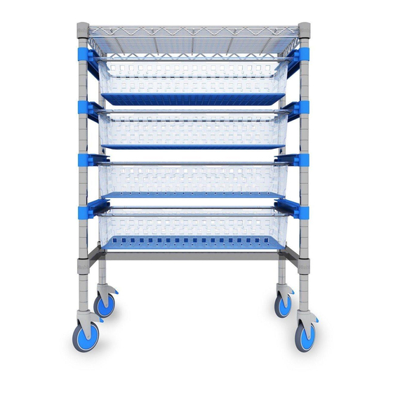
Nimble 60-40 Storage Assembly Instructions
INFORMATION
It is recommended that 2 people assemble units with shelf sizes 908mm and longer.
Assemble the unit in a clear space on level ground.
Take note the black clips that support the H-Bars and C-Bars and wire shelves have
an indicator printed on them. Snap the black clips onto the posts with the indicator
facing up.
Each flat pack tray can hold up to 25 kilograms of weight when assembled.
Wipe clean with a soft cloth dampened with water and a mild detergent if
necessary. Wipe dry with a clean cloth.
Advertisement

Summary of Contents for nimble 60-40
- Page 1 Nimble 60-40 Storage Assembly Instructions INFORMATION It is recommended that 2 people assemble units with shelf sizes 908mm and longer. Assemble the unit in a clear space on level ground. Take note the black clips that support the H-Bars and C-Bars and wire shelves have an indicator printed on them.
-
Page 2: Parts Included
PARTS INCLUDED 4 x Posts 2x non-brake & 2x brake castors for Mobile units ONLY Black clips Runs front to back of unit Cross support bar is at the back of the unit Cross support bar runs left to right C-Bar –... - Page 3 6 groove to place additional 100mm trays. To make a 60-40 unit mobile unscrew the feet from the posts and simply screw in the castors. Ensure break castors are positioned on the front two posts of the unit.
- Page 4 H-BARS & C-BARS 1. Measure the desired height of where the bottom H-Bar 2. Position the black clip onto the groove on the post will sit on one of the posts. closest to the desired height. *Recommended height is 250mm clearance off the floor. *The grooves are spaced at 1 inch intervals on the posts.
- Page 5 6. Slide it all the way along until the collar surrounds the 7. Repeat steps 4 – 6 on all remaining posts. black clip on the upper end of the post. 8. Once all the black clips are securely in the collars of 9.
- Page 6 12. Locate the final set of black clips on the top of the 13. Lower the H-Bar down with the posts sitting inside the posts for the final H-Bar. Follow steps 2 – 4. collars until the collars of the H-Bar surround the clips on the upper end of the posts.
- Page 7 RAIL SETS Rail sets will be packaged with corresponding front and back knuckles. To check the correct installation, hold the rail up to the unit – the runner and stopper should face inward. This runner will hold the tray in the unit. 1.
- Page 8 7. Take the rail and place this over the 2 ends facing 8. Once sitting on the knuckle pull the rail down, close to toward each other and slide over the top of these ends. each knuckle, to clip the rail over the knuckles securely. You should feel a click when it does connect.
-
Page 9: Tray Assembly
TRAY ASSEMBLY 1. Place two long side panels down on flat surface with 2. Place the two short panels over the long panels so they the lip sections facing up and on the outer edge. overlap the long edges. 3. Lay the wire ring on the inner section of the lips on the 4. - Page 10 7. Push the ring into the securing clips ensuring that the 8. Flip the tray over and place the blue mesh base into ring is pushed and clipped into each securing clip. the bottom of the tray. 9. Ensure the round edge of the blue mesh base is facing 10.