Table of Contents
Advertisement
Advertisement
Table of Contents

Summary of Contents for Nordmann Engineering SPA Display
- Page 1 Nordmann SPA Display INSTALLATION AND OPERATION MANUAL 2591871-A EN 1903...
- Page 2 Nordmann Engineering AG, except to the extent required for installation or maintenance of recipient's equipment. Liability Notice Nordmann Engineering AG does not accept any liability due to incorrect installation or operation of the equipment or due to the use of parts/components/equipment that are not authorised by Nordmann Engineering AG. Copyright Notice ©...
-
Page 3: Table Of Contents
Notes on positioning the Nordmann SPA Displays Mounting the Nordmann SPA Display 4.4.1 In-wall mounting 4.4.2 On-wall mounting Connecting the Nordmann SPA Display to the Nordmann Omega or to the Condair Delta SPA Control Box Configuration and operation of the Nordmann SPA Display 5.1 Configuration of the Nordmann SPA Display Operation of the Nordmann SPA Display... -
Page 4: Introduction
We thank you for having purchased the Nordmann SPA Display with touch-sensitive display. The Nordmann SPA Display incorporates the latest technical ad van ces and meets all recognized safety standards. Nevertheless, improper use of the Nordmann SPA Display may result in danger to the user or third parties and/or impairment of material assets. - Page 5 Safekeeping Please safeguard this installation and operation manual in a safe place, where it can be immediately accessed. If the Nordmann Omega or the Condair Delta SPA Control Box with which the Nordmann SPA Display is used changes hands, the documentation should be passed on to the new operator. If the documentation gets mislaid, please contact your Nordmann representative.
-
Page 6: For Your Safety
For safety and warranty reasons any action beyond the scope of this manuals must be carried out only by qualified technical personnel authorised by your Nordmann representative. It is assumed that all persons working with the Nordmann SPA Display are familiar and comply with the appropriate regulations on work safety and the prevention of accidents. - Page 7 Nordmann SPA Display is no longer operating correctly – if the connecting cable is damaged All persons working with the Nordmann SPA Display must report any alterations to the unit that may affect safety to the owner without delay. Prohibited modifications to the unit No modifications must be undertaken on the Nordmann SPA Display without the express written consent of the manufacturer.
-
Page 8: Product Overview
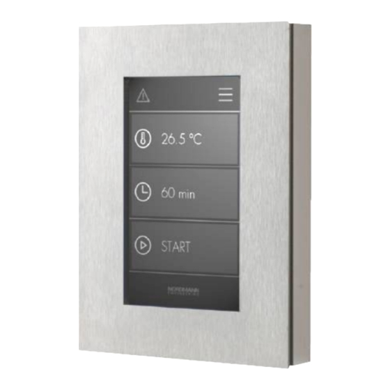
Product Overview Nordmann SPA Display Nordmann SPA Display in-wall mounted on-wall mounted Fig. 1: Front view Fig. 2: Front view Fig. 3: Back view Fig. 4: Back view Touch-sensitive display Magnets for the attachment of the decora- tive cover In-wall mounted housing... -
Page 9: Installation
In case you wish to dispose of the packaging, observe the local regulations on waste disposal. Never dispose of the packaging to the environment. Storing the unit If the Nordmann SPA Display must be stored, store it in a protected area (best in the original packaging) meeting the following requirements: –... -
Page 10: Notes On Positioning The Nordmann Spa Displays
Do not mount the Nordmann SPA Display(s) on vibrating components. – Place the Nordmann SPA Display(s) in such a way, that the total length of 50 m of the CAN BUS cables with which the Nordmann Omega or the Condair Delta SPA Control Box and the Nordmann SPA Display(s) are interconnected is not exceeded. -
Page 11: In-Wall Mounting
4.4.1 In-wall mounting 1. At the desired location, mark mounting opening according to the size of the in-wall mounted housing with the help of a spirit level, then ream out the mounting opening. Important: the mounting opening must be reamed out exactly since the decoration cover (broken line in Fig. - Page 12 3. Insert the in-wall mounted housing into the wall opening, align it with the help of a spirit level, then fix it with the four fastening claws attached to the in-wall mounted housing (only necessary with cavity walls). Note: in massive walls the in-wall mounted housing must be fixed either with the screws and dowels supplied or by using PU mounting adhesive or mortar.
- Page 13 5. Connect the supplied CAN BUS connecting plug to the CAN BUS cable from the Nordmann Omega, Condair Delta SPA Control Box or from another Nordmann SPA Display as shown below. For this purpose, strip the individual cable wires of the CAN BUS cable 6 mm, crimp the suitable wire end ferrules and insert the cable wires as far as possible into the correct connection opening of the sup- plied CAN BUS connecting plug.
- Page 14 A CAN BUS cable to another Nordmann SPA display is connected either directly or via another adapter cable (available as an accessory) to the unused terminal "X2" (see notes in chapter 4.5). Important: If two CAN BUS cables are connected to the Nordmann SPA Display board, jumper "JP1"...
- Page 15 Condair Delta SPA Control Box, then perform the function tests of the Nordmann Omega SPA Display. 7. After function tests have been passed carefully place the Nordmann SPA Display onto the in-wall mounted housing. Make sure the supply cable is not getting pinched. Then, fix the Nordmann SPA Display to corresponding supports of the in-wall mounted housing using the four screws supplied.
- Page 16 8. If necessary loosen the screws of the display supports and adjust the display. Fig. 12: Adjusting the display 9. Finally attach the decoration cover (the decoration cover is held by the magnets in the in-wall mounted housing), and seal the gap between the decoration cover and the wall splash-proof with silicone. Fig.
-
Page 17: On-Wall Mounting
4.4.2 On-wall mounting 1. Using the aluminum on-wall mounted housing as template mark the two fixing holes at the desired location, with the help of a spirit level. Then proceed as follows: – for the mounting on a stonework wall: • Drill 2 holes ø6 mm, depth 35 mm. - Page 18 2. Free the shielding of the CAN BUS cable(s) (shielded four-wire cable, 0.34 mm per wire) by removing the insulation from the appropriate clamping position to the end of the cable. Remove the exposed shielding to about 2 cm, then fix the end of the remaining shielding with a piece of shrink tubing as shown in Fig.
- Page 19 3. Mount the on-wall mounted housing to the wall: – for the mounting on a stonework wall: • Insert the supplied dowels. • Fix on-wall mounted housing to the wall using the screws supplied, align housing with the help of a spirit level and fasten den screws. –...
- Page 20 4. Connect the supplied CAN BUS connecting plug to the CAN BUS cable from the Nordmann Omega, Condair Delta SPA Control Box or from another Nordmann SPA Display as shown below. For this purpose, strip the individual cable wires of the CAN BUS cable 6 mm, crimp the suitable wire end ferrules and insert the cable wires as far as possible into the correct connection opening of the sup- plied CAN BUS connecting plug.
- Page 21 A CAN BUS cable to another Nordmann SPA display is connected either directly or via another adapter cable (available as an accessory) to the unused terminal "X2" (see notes in chapter 4.5). Important: If two CAN BUS cables are connected to the Nordmann SPA Display board, jumper "JP1"...
- Page 22 Condair Delta SPA Control Box, then perform the function tests of the Nordmann Omega SPA Display. 6. After function tests have been passed carefully place the Nordmann SPA Display onto the on-wall mounted housing (make sure the supply cable is not getting pinched). Then, fix the Nordmann SPA Display to the on-wall mounted housing using the four screws supplied.
-
Page 23: Connecting The Nordmann Spa Display To The Nordmann Omega Or To The Condair Delta Spa Control Box
Observe and comply with the notes in the installation and operation manual of the Nordmann Omega or the Condair Delta SPA Control Box and the local regulation regarding electrical instal- lation when connecting the Nordmann SPA Display(s) to the Nordmann Omega or the Condair Delta SPA Control Box! - Page 24 SPA Control Box. Also observe the instructions in the installation manual for the Nordmann Omega or the Condair Delta SPA Control Box. Condair Delta SPA Control Box / SPA Display - D1 Nordmann Omega SPA Display - D2 Jumper "JP1" must be set Jumper "JP1"...
- Page 25 SPA Display - D1.2...D1.x (X3) Condair Delta SPA Control Box / SPA Display - D1 Nordmann Omega SPA Display - D2 Jumper "JP1" must be removed if two CAN BUS cables are connected Jumper "JP1" must be removed if two CAN BUS cables are connected SPA Display - D2.2...D2.x...
- Page 26 7. Remount front panel of the Nordmann Omega or Condair Delta SPA Control Box, respectively. 8. Put the Nordmann Omega or Condair Delta SPA Control Box, respectively into operation. Assumed the cabling is correct the home screen is shown on the Nordmann SPA Display after start- up of the Nordmann Omega.
-
Page 27: Configuration And Operation Of The Nordmann Spa Display
In principle, the Nordmann SPA Display is ready for operation after the connection and requires no ad- ditional configuration. However, if more than one SPA display is used in the system, a unique display address must be assigned to each connected SPA display. -
Page 28: Troubleshooting
Troubleshooting Fault indications / warning and fault list Detailed information on the fault indication on the Nordmann SPA Display as well as a list of the warning and fault messages which can occur during operation of the Nordmann Omega or the Condair Delta SPA Control Box can be found in chapter 8 of the Nordmann Omega or the Condair Delta SPA Control Box operation manual. -
Page 29: Taking Out Of Service/Disposal
7.1 Taking out of service If the Nordmann SPA Display must be replaced or if the Nordmann SPA Display is not needed any more, proceed as follows: 1. Switch off the Nordmann Omega steam generator, separate it from the mains and secure it against inadvertent power-up. -
Page 30: Technical Data
Technical data Nordmann SPA Display in-wall mounted version on-wall mounted version Touch Panel Resistive Touch Panel with 95 x 54 mm active screen Display 4,3" LCD, 272 x 480 Pixel Interface CAN BUS Supply voltage 24 VDC Max. rated power Admissible ambient temperature -20…70°C... -
Page 31: Spare Parts
Decorative cover glass white 2590185 Decorative cover glass black 2590186 PCB SPA Display 2590964 Shielding clamps 2595477 SPA Display adapter cable 2595479 ––– Plug for CAN BUS cable (5 pcs.) 2591662 ––– CAN BUS cable shielded (50 m) 2591666 –––... - Page 32 Notes...
- Page 33 Notes...
- Page 34 Notes...
- Page 36 CH94/0002.01 Nordmann Engineering AG Lindenhofstrasse 28, 4052 Basel, Switzerland Phone +41 61 404 46 50, Fax +41 61 404 46 79 www.nordmann-engineering.com, info@nordmann-engineering.com...
Need help?
Do you have a question about the SPA Display and is the answer not in the manual?
Questions and answers