Advertisement
Quick Links
Brief introduction
Many thanks for purchasing Gigabit optical converter!
This product supports IEEE802.3Z/AB 1000Base-SX/LX
protocol, the working mode of duplex full mode and half
mode. The electric outlet is adaptive to the rate of
10/100/1000M Gigabit optical converter. This manual is
for various models of adaptive 10Base-T, 100Base-T, and
1000Base-T optical converters. The following purchasing
guide is for customer to refer to.
Purchasing guide for Gigabit optical converters
Model
Specifications
TP- LC MM 1000M adaptive, multi-mode 500 meter
TP- LC SM 1000M adaptive, single mode dual fiber 0-80 Km
Packing list
Please check the following items in the package before
the installation of converter.
Gigabit optical converter
1 piece
AC/DC adapter (external)
1 piece
User manual
1 copy
Please contact the dealer immediately for any loss or
damage to the above items.
Installation
1. Interface
RJ-45 interface
The transmission media adopts CAT5 and CAT 6
twisted-pair. It is recommended to use quality RJ-45 and
well made jumper. It features the function of
automatically identifying the through line and cross wire.
Fiber interface
If the SFP fiber transceiver you used is dual fiber type,
including two interfaces namely TX and RX. When the
two sets of optical converter are interfaced or connected
to switchboard with fiber interface, the fiber is in cross
connection, namely "TX-RX" "RX-TX".
2. Connection
Connect the network device (work station, hub or switch)
to the RJ-45 jack of the optical converter through
twisted-pair CAT5. Insert the SFP fiber transceiver in the
metal cage. Connect the multi-mode/single-mode fiber to
the SC/LC fiber interface of the SFP fiber transceiver.
Turn the power on. The corresponding LED is on for a
correct connection. (See the table below for the LED
indicator lamp)
Figure 1 Schematic drawing of connection
Explanation for LED indicator lamp
1
The LED indicator lamps serve as device monitoring and
error display. The following explains each LED indicator.
LED
Status
Explanation
SPD
On
The rate of the TP port is 1000Mbps
Off
The rate of the TP port is 10/100Mbps
LINK/ACT
Blink
Active
status
interface link
"Blink" indicates packet goes through
TP
F1
Blink
Active status display of the corresponding
fiber interface link.
"Blink" indicates packet goes through
FX
F2
Blink
Active status display of the corresponding
fiber interface link.
"Blink" indicates packet goes through
FX
PWR
On
Power is on and normal.
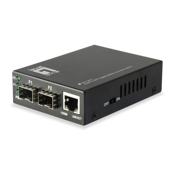
Redundant DIP-Switch description:
When the DIP-Switch is on the "OFF" side (Default), the
2 fiber ports are working on the switch mode; When the
DIP-Switch is on the "ON" side, the 2 fiber ports are
working on the redundant mode.
When the Redundant function enabled, the F1 port work
as main channel, if the F1 port link down, the F2 port will
link up within 10ms, if the F1 port recovered, the F2 port
will link down and F1 link up within 10ms.
display
of
electrical
Advertisement

Summary of Contents for level 1 GVT-2011
- Page 1 well made jumper. It features the function of The LED indicator lamps serve as device monitoring and Brief introduction automatically identifying the through line and cross wire. error display. The following explains each LED indicator. Many thanks for purchasing Gigabit optical converter! Status Explanation This product supports IEEE802.3Z/AB 1000Base-SX/LX...
- Page 2 -6-12 <-18 20Km TP-LC SM 1310 -3-8 <-21 40Km GVT-2011 Trouble shooting: TP-LC SM 1550 <-30 80Km 1. Line loss is excessive during the fiber wiring Excessive loss in adaptor connector plug-in and fiber RJ45 to SFP Gigabit Media...
Need help?
Do you have a question about the GVT-2011 and is the answer not in the manual?
Questions and answers