Table of Contents
Advertisement
Quick Links
Advertisement
Table of Contents

Related Manuals for SPL PASSEQ


Summary of Contents for SPL PASSEQ
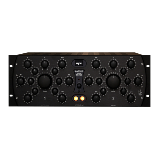
- Page 1 PASSEQ Passive Mastering Equalizer • Test Report • Manual / Handbuch...
- Page 3 PASSEQ Passive Mastering Equalizer Manual...
-
Page 5: Table Of Contents
Content PASSEQ Version 1.2 – 12 / 2017 Package Contents Introduction King of the passive equalizers Technical Aspects 120 Volt Technology 120 Volt Technology - Diagrams The Basics of Frequency Filtering Filter Types Shelf Filters Peak Filters Bandwidth Passive EQs... -
Page 6: Version 1.2 - 12 / 2017
Unless stated otherwise, everything herein corresponds to the technical status at the time of delivery of the product and user manual by SPL electronics GmbH. The design and circuitry are under continuous development and improvement. Technical specifications are subject to change. -
Page 7: Introduction
With 12 switchable frequen- cies per band, totaling 36 boost and 36 cut frequencies, the Passeq was the most power- ful passive EQ system ever made. The new PASSEQ Mastering Equalizer features the same... -
Page 8: Technical Aspects
Technical Aspects 120 Volt Technology SPL‘s goal was to push analog signal processing to the limits. That‘s why we combined the best possible components with a high-grade optimized circuit design. We have been using the in-house developed 120-volt technology - the highest-ever oper- ating voltage used for audio applications - in all our products from the Mastering series for years. -
Page 9: 120 Volt Technology - Diagrams
10 dB higher. THD measurements of the SPL op-amps show a difference of more than 3 dB compared to the OPA134 at 36 V — in terms of sound pressure level, that corresponds to an improvement of more than 50%. -
Page 10: The Basics Of Frequency Filtering
The Basics of Frequency Filtering Filter Types There is basically only one type of filter used in the PASSEQ: The bell-filter or peak-filter. But since the center frequency of the peak-filter, concerning the HF and LF bands, is only marginally within the perceptible hearing range, these filters auditorily and visually rather correspond to shelf-filters. -
Page 11: Passive Eqs
The Basics of Frequency Filtering Passive EQs A filter in a passive network got no amplification elements and therefore does not need any external power. That is why you can only attenuate the energy of the frequencies. However, to change the energy of the frequencies of a passive filter network in both ways (attenuate and increase), the signal level of the filter input signal gets reduced by a certain value. -
Page 12: Installation
The PASSEQ can be powered on and off with the use of a circuit breaker, as long as the total load does not exceed the rating of the latter. -
Page 13: Cabling: Rear Side
3=cold (-) Ground Lift switch to avoid ground loops On the rear panel of the PASSEQ Mastering Equalizer (see page 10) is also a „GND LIFT“ (Ground Lift) switch to avoid any ground loops. Ground loops take place when gear con- nected in the same network have different potentials. - Page 14 C AUTION RISK OF ELECTRIC SHOCK D O N O T O P E N AVIS: RISQUE DE CHOC ÉLECTRIQUE • NE PAS OUVRIR PASSEQ WA R NIN G TO REDUCE RISK OF FIRE OR ELECTRIC SHOCK. Serial DO NOT EXPOSE THIS UNIT RAIN OR MOISTURE.
-
Page 15: Control Elements
Control Elements HF - HF + HF - PASSEQ passive MF - MF + MF - mastering equalizer Auto Byp. Output LF - LF + LF - 120V DC Audio Rail Sound Performance Lab HF- Frequency Output HF- Gain Power LED... -
Page 16: Layout Of Control Elements
Because modern productions often demand a definite number of choices in an engineer’s options for achieving an optimal result in bass emphasis, the PASSEQ has been designed with a very complete set of low frequency options to insure realizing these goals. -
Page 17: Mf+ And Mf
PASSEQ on its devel- oper, Wolfgang Neumann‘s years of musical experience. The middle bands‘ peak struc- ture is chosen for a clean separation of LF and HF bands. -
Page 18: Gain
Control Elements Gain The maximum increase or attenuation of the amplitude is adjusted to the according fre- quency range for each frequency band. The setting can be selected with detented poten- tiometers in 41 steps. Maximum change in amplitude: • LF- (Low Frequencies Cut): 22 dB •... -
Page 19: Recommendations On Using Equalizers
Recommendations on using Equalizers Basic Approaches and Working Techniques While we would never assume that in creative and artistic work there should be absolute rules, and this also applies to work with EQ: There is no such thing as “The Voice” or “The Kick Drum”... -
Page 20: Specifications
Specifications Measurements Inputs Max. Input Level ........+ 32,5 dBu Input Inpedance ........20 kOhms (balanced) Outputs Max. Output Level ........+ 32,5 dBu Output Inpedance ........‹ 600 ohms (balanced Harmonic Distortion: at -30 dBu: 0,076% at -20 dBu: 0,026% at 0 dBu: 0,026% at +10 dBu: 0,0086% at +30 dBu: 0,0012%... -
Page 21: Security Advices
Such actions can lead to dangrous electrical shocks or fire! Ventilation The vent openings on the unit are meant to avoid the PASSEQ from overheating. You should never cover nor block these openings. Power Supply Power the unit exclusively with the voltage rating specified on the unit. - Page 22 Security Advices Controls and switches Operate the controls and switches only as described in the manual. Incorrect adjustments outside safe parameters can lead to damage and unnecessary repair costs. Never use the switches or level controls to effect excessive or extreme changes. Repairs Unplug the unit from all power and signal connections and immediately contact a quali- fied technician when you think repairs are needed –...
-
Page 23: Contact
Facebook: facebook.spl.info © 2017 SPL electronics GmbH This document is the property of SPL and may not be copied or reproduced in any manner, in part or fully, without prior authorization by SPL. Sound Performance Lab (SPL) con- tinuously strives to improve its products and reserves the right to modify the product described in this manual at any time without prior notice.
Need help?
Do you have a question about the PASSEQ and is the answer not in the manual?
Questions and answers