
Related Manuals for PEERLESS PVF Series

Summary of Contents for PEERLESS PVF Series
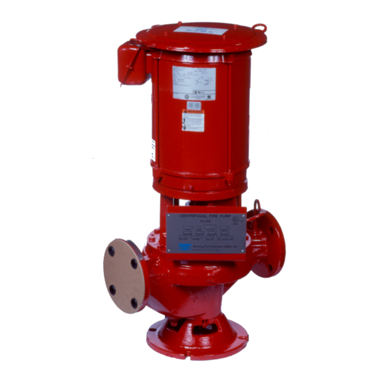
- Page 1 Peerless_USLetter_Front_PVF IO.fm Page 1 Friday, September 13, 2019 10:38 PM Vertical inline single stage pumps Installation, operation and maintenance manual (English)
-
Page 2: Table Of Contents
English (US) Installation and operating instructions Original installation and operating instructions Table of contents General information ......2 1. -
Page 3: Hazard Statements
1.2 Hazard statements DANGER The symbols and hazard statements below may appear in Peerless Electric shock installation and operating instructions, safety instructions and Death or serious personal injury service instructions. ‐ The electrical installation must be carried out by a... - Page 4 Do not remove or paint over any safety labels. If labels are hooks or slings on shafts or conduit box. Straps should lost or damaged, contact your Peerless Pump not be used to lift a pump assembly. representative for replacement.
-
Page 5: Identification
Each pump has a nameplate with the pump serial number (see Information on the flange nameplate includes the following: nameplate example). Reference the serial number when contacting Peerless Pump with questions or a service request. A nameplate • pump size/model can also be found on the driver, if supplied. - Page 6 2.4 Type key for in-line fire pump Example: 8PVF16G 1-A-1/7-P-A-B-R-C Code Example Designation 8 inches Inlet and outlet flange [inch] Vertical In-line single stage pump Pump type 16 inches Maximum impeller diameter [inch] <> - None (blank) Impeller design A/B/C/G Mechanical seal 125 lb, inlet;...
-
Page 7: Type Key For In-Line Fire Pump
For Engineered to Order (ETO) products, Peerless The pump has been prepared for shipment at the factory so as to Pump recommends that you invite a Peerless Pump service minimize potential damage due to handling and transport. engineer to supervise the installation and startup to ensure a proper WARNING installation. -
Page 8: Foundation
If you need assistance to calculate or measure 4.4 Installation preparations suction supply system NPSH, contact your Peerless 4.4.1 Pre-installation check Pump representative. All pump parts are carefully inspected before leaving the factory but... -
Page 9: Mechanical Installation
4.4.6 Doweling preparations 12. Reorient the level on the same surface, 90 ° from the original position. Contact Peerless Pump for further information about doweling. 13. Again adjust the wedges or shims until the level reading is 4.4.7 Floor mounting 0.005 inch (0.12 mm). -
Page 10: Pipes And Connections
Inlet and outlet pipes must be anchored, supported and restrained Cross board for holding foundation bolts near the pump to avoid application of forces and moments to the pump in excess of those permitted by Peerless Pump. Template frame Do not exceed the forces or moments specified on the... -
Page 11: Lubrication, Priming And Cooling Systems
Minimize pump nozzle loads by aligning the pipes with the pump • lubrication of the driver nozzles. Contact Peerless Pump for allowable nozzle load for your • oil-cooling connections for the driver, if applicable particular system design. -
Page 12: Checking Rotation
Achieving the desired results will sometimes take several days. WARNING Electric shock Peerless Pump recommends the use of lantern rings and Death or serious personal injury water seal lines ‐ Switch off the power supply before you start any work on the product. -
Page 13: Service
5.4.7 After starting the pump Gauges (if used) of correct range and in good condition. All foundation, pump, and driver bolts properly tightened. All CAUTION external fasteners (nuts, bolts, screws) on pump checked Equipment damage and malfunction against recommended torque values. Minor or moderate personal injury ‐... -
Page 14: Recommended Spare Parts
Before starting disassembly of the pump, we recommend obtaining a set of spare parts as shown in section 8.2 Recommended spare • cleaning materials parts. Peerless Pump does not recommend the reuse of gaskets, • touch-up coating O-rings, and packing rings. -
Page 15: Wear Ring
Remove plug from bottom of casing and drain casing. Ensure the ID of the volute ring is concentric with the Disconnect inlet and outlet lines. wear ring OD, and the surface is smooth. The pump need not be disconnected from inlet and outlet pipes for disassembly. -
Page 16: Accessories
• If the pump is assembled, place and securely fasten without notice by Peerless Pump at their option. additional desiccant in the outlet of the pump. Make sure that the gland enters the stuffing box at all •... -
Page 17: Handling The Product
Related information 7.1 Storage 7.1.4 Long-term storage • Long-term storage protection provided by the factory does not extend the warranty in any manner. • The warranty is valid only if the equipment is properly handled and stored. • In case of storage up to six months or longer, the pump must be protected against heat and moisture as described in the previous sections. -
Page 18: Fault Finding / Fault Finding The Product
8. Fault finding / Fault finding the product If connected directly to electric motors, determine whether or not the motor is direct-on-line and receives full voltage. Fault Cause Remedy Reestablish the correct speed and direction The speed of rotation is too low. of rotation. - Page 19 Fault Cause Remedy • Increase the liquid level on the inlet side. The system pressure exceeds the shut-off • Open the isolating valve in the inlet pipe. pressure. • Check system head curve vs. performance curve. The speed of rotation is too low. Reestablish the correct speed of rotation.
-
Page 20: Parts List And Sectional Drawings
Peerless Pump | 2005 Dr. Mar n Luther King Jr. Street | Indianapolis, IN 46202 317-925-9661 | www.peerlesspump.com It is the policy of Peerless Pump to continually seek ways to improve its products and reserve the right to alter documentation without prior notice.
Need help?
Do you have a question about the PVF Series and is the answer not in the manual?
Questions and answers