Table of Contents
Advertisement
Quick Links
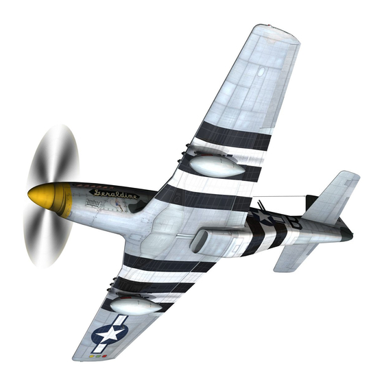
North American P 51 D Mustang
Paper Scale Model Kit
The Items needed for assembly:
1. Glue stick
2. Liquid glue
3. Instant Bond type glue
4. Sharp Scissors
5. A ruler with a good straight edge
6. Round tooth picks
7. Cardboard from the back of a pad of paper or from a cereal box
8. Tweezers
9. An Exato knife or razor blade
Tips:
1. When cutting out the pieces to be assembled always cut slightly on the color side of
the line. Leaving a white edge will detract from the appearance of the model. Use
caution when cutting. Only remove enough color to eliminate the white edge. Cutting
the pieces undersize will alter the fit when gluing them together.
2. Any white area bordered by a black line is not to be cut off. This area is intended for
attachment beneath the adjoining piece.
3. Because of the need for rounded surfaces many of the pieces have to be assembled in
a cup like fashion. This is accomplished in the same manor you use to cup your
hands. By drawing together and overlapping the two pieces starting at their narrowest
overlap moving to the widest, the piece will take on a cup like appearance.
4. Use the solid glue stick unless otherwise specified. This helps eliminate applying too
much glue.
5. When applying glue, whenever possible, place it on the piece that will be on top of
the next. This also helps avoid applying too much glue.
6. Scoring creased folds using a straight edge helps make very straight creases. A letter
open is what I prefer.
By 3D Creations
1
Advertisement
Table of Contents

Summary of Contents for 3D Creations North American P 51 D Mustang
- Page 1 North American P 51 D Mustang By 3D Creations Paper Scale Model Kit The Items needed for assembly: 1. Glue stick 2. Liquid glue 3. Instant Bond type glue 4. Sharp Scissors 5. A ruler with a good straight edge 6.
-
Page 2: Fuselage Assembly
Fuselage Assembly Cut out parts #1, #2, #3,and #4. Glue the wing mount sections (parts #3 & #4) to the fuselage parts #1 & #2 matching up the paint scheme to insure that they are mounted on the correct side. Next cut out parts #6, #7, and #24. - Page 3 slightly warp the fuselage to get the desired fit of the tabs and that is exactly what we want. Now cut out part #24. Look carefully and you will find a short gray line that runs lengthwise on the center of the piece. This is where the antenna mast will be mounted later.
-
Page 4: Landing Gear Assembly
Locate part #5 and cut it out. Shape the piece in to a U before mounting. (Do not crease). The white tabs at the tail are to be creased upward at a 90-degree angle for the tail mount that comes later. Cut out part #26. - Page 5 Parts #9 are to be glued down flat to cardboard and then cut to shape. Part #9 is not necessary if you are not going to build the kit with landing gear. Sandwich the landing gear strut between two of the wing spars (part #9) as shown in figure 17. Make sure that the two spar edges are matched up evenly and the struts hang at a 90-degree angle from them.
-
Page 6: Wing Assembly
Wing Assembly For the wing assembly you will need to cut out parts # 8 and 10. Before folding the wing to shape cut out the black dots that lie in the white areas of the wing. An exacto knife works well for this. - Page 7 Carefully inspect the edges of the wings and trim any of the edges that don’t match up perfectly. Now cut out parts #11 and #12. On these parts you will notice white glue tabs that are to be left connected to the green central spar.
-
Page 8: Mounting The Wing
spars and butt them together. Cut out parts #16 and 17. Glue part #17 over the seam between the two wings. Trim the edges if necessary. Flip the wing over and check the dihedral. It should be right at one inch. See figure 24. Glue part #16 over the seam on the top of the wings making sure you hold that 1 inch dihedral while doing it. - Page 9 Elevator and Rudder Construction Cut out elevator parts #14 and 15. Score and fold along the lines indicated in figure 26. Apply glue to the trailing edge tab and the very edge of the elevator wing tip. Fold the elevator halves together then fold the trailing edge tab back in to place.
- Page 10 Final Landing Gear Assembly Cut out parts #32. Apply glue to the backside of these parts and apply them to the landing gear struts as shown in figure 30.Cut out parts #36,37 and 38 as a group using the black boarder that surrounds them.
- Page 11 The next step is optional. The wheel doors can be put on or left off. When the doors are open they are in the service position. When the aircraft is taxing or takes off these doors are closed. This was not an option on the earlier models of the Mustang.
- Page 12 Cut out parts #33,34,34A and 35 along the black boarder that surrounds them. Glue these parts to a piece of cardboard then cut them out individually. Cut a toothpick to length and super glue it to the backside of part #33 as shown in figure 35. Next glue parts #35 to the backside of part #33 on each side of the toothpick.
-
Page 13: Canopy Assembly
Canopy Assembly Cut out part #21 the canopy. Take care not to cut the gluing tabs off while doing this. Fold the windscreen sections back 90- degrees. See figure 38. Using the cupping technique to draw the sections together glue the canopy to shape. - Page 14 Propeller and Spinner Assembly Cut out parts # 47, 48 and 50 using the black boarder that surrounds them. Glue these parts flat to your cardboard. After the glue is set cut out the pieces to shape. Glue all the #48 pieces together by stacking them one on top of another.
- Page 15 Glue the spinner to parts # 47 and 48 with the blue glue tabs as shown in figure 42. The propeller and spinner when correctly mounted will not be in the center. It should be offset enough to leave the air intake exposed. If you build the kit to fly you must balance the ship.
Need help?
Do you have a question about the North American P 51 D Mustang and is the answer not in the manual?
Questions and answers