
Related Manuals for OneTemp GDA 2500 Series

Summary of Contents for OneTemp GDA 2500 Series
- Page 1 GDA 2500 Series Loop Powered Sensor Operating Manual Manual Revision: 1.0 Hardware Version: 2.6 © Copyright Gas Detection (Australia) Pty Ltd 2019...
- Page 2 Thank you for purchasing this product from Gas Detection (Australia) Pty Ltd This manual contains information about the method of installation and operation of the GDA 2500 series of gas sensors. Please read it carefully and keep it nearby for further reference. Note: The calibration period for a sensor will depend on a number of factors such as the environment in which it is used, operating temperature, humidity, atmospheric pressure and...
- Page 3 WARNINGS The GDA 2500 Series Sensors are only to be used in areas classified as SAFE AREAs. The sensor is not designed for use in classified HAZARDOUS AREAs. If GDA 2500 Series Sensors are used for safety critical applications the Calibration/Bump test period should be evaluated according to risk management procedure associated the area the sensor is installed.
-
Page 4: Table Of Contents
Table of Contents Overview: ..............................5 1.1. Introduction .............................. 5 1.2. Specifications: ............................6 1.3. Sensor Specifications: ..........................7 Sensor Placement: ............................8 Wiring Instructions: ............................ 9 Operation: ..............................10 Calibration and Functional Test: ....................... 11 5.1. Zero point Calibration ..........................12 5.2. -
Page 5: Overview
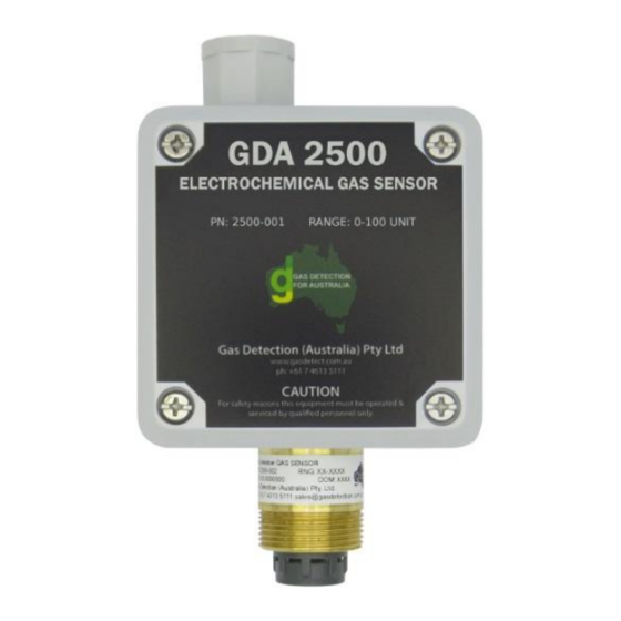
1. Overview: 1.1. Introduction The GDA 2500 Series gas sensors have a loop powered 4-20 mA transmitter with an electrochemical gas sensor module. The gas sensor transmitter is a current loop powered device which provides a 4-20 mA current value corresponding to the target gas concentration present. It accepts a range of electrochemical sensor modules see Table 2 for gas types and ranges. -
Page 6: Specifications
1.2. Specifications: Series GDA 2500 Operating Voltage +24 V from a regulated power supply Output Type 4-20 mA Loop Powered Power Consumption <25 mA @ 24 V Connection 3 pin plug connector; 24 V , mA O/P & Earth Wiring 2 core 18 AWG with overall screen Max loop impedance 680 Ω... -
Page 7: Sensor Specifications
1.3. Sensor Specifications: Table 2: Gas Sensor specifications Model 2525 2526 2527 2528 2529 2530 2531 Carbon Nitrogen Hydrogen Sulphur Detection Gases Ammonia Oxygen Chlorine Monoxide Dioxide sulphide Dioxide Chem. Formula 0-100 0-100 Ranges 0-150 0-300 0-30 0-25 0-100 0-10 0-10 0-200 0-1000... -
Page 8: Sensor Placement
2. Sensor Placement: The recommended sensor instillation height is determined from: The properties of the target gas (Table 2). Properties of other gases present. The temperature of the gasses present. Air flow in the detection space. ... -
Page 9: Wiring Instructions
3. Wiring Instructions: The sensor is a two-wire loop-powered 4-20 mA device. The sensor is designed to work with 24 V from a regulated power supply. The sensor transmitter is wired to the GDA range of control units with a 2 core cable with an overall screen/shield or a 3 core 18 AWG cable. The screen or third wire should be connected to the Earth connection of the sensor. -
Page 10: Operation
4. Operation: The sensor has three LEDs which indicate the status of the sensor. After an initial warm up period. Sensor output Function The red and amber LEDs indicate that the sensor >12.00mA to 20.00mA has detected the target gas at half scale or above. The amber LED indicates that the sensor has detected the target gas at below half scale and zero <12.00 mA to 4.00mA... -
Page 11: Calibration And Functional Test
5. Calibration and Functional Test: Sensors are issued tested & pre-calibrated under controlled lab conditions. Changes to humidity, temperature, and other environmental factors affect the sensor accuracy and may need an adjustment of the Zero point when introduced to new environments. THE SENSOR MUST BE FULLY POWERED FOR A MINIMUM OF ONE (1) HOUR BEFORE CALIBRATION IS CARRIED OUT. -
Page 12: Zero Point Calibration
5.1. Zero point Calibration The Zero point is when there is none of the target gas present (e.g. 0 ppm CO, 0% vol. O A Zero point calibration adjusts the 4.0 mA point of the transmitter to correspond to a zero target gas concentration. -
Page 13: Span Point Calibration
5.2. Span point Calibration The Span point is set when the sensor is exposed to a known concentration of the target gas. This is normal at half or full scale of the sensor (e.g. 100 ppm CO, 18% vol. O Calibration using the 4-20 mA test points and a multimeter see Figure 6 for mA output test points and adjustment pots. -
Page 14: Test Ma Output
5.3. Test mA Output The sensor transmitter board has a current output test function. This is used to simulate the current output signal of the transmitter board for functional testing of the system. The simulated mA current has an adjustable range from 4 to 20 mA. To use the test current function, set jumper JP2 to the Test position see Figure 7 below. -
Page 15: Sensor Head Replacement (25Xx-002)
6. Sensor Head Replacement (25xx-002): When the sensor head is being replaced, the replacement sensor heads are supplied tested but will require calibration when installed, follow these instructions on how to remove used sensor and install new sensor without damaging the sensor. Gloves are recommended when removing the brass sensor head to protect your hand from cuts. - Page 16 mA Output Test 4-20 mA Adjustment Pot Test Point Figure 7 Figure 6 Incoming Cable Connection See Figure 4 JP1 Jumper Figure 5 JP2 Jumper Figure 5 LEDS Jumpers JP4 & See Table 3 JP3 See Figure 6 Span Adjustment Zero Adjustment Pot See Figure 6...
- Page 17 Gas Detection (Australia) Pty Ltd Page 17 of 20 M-GDA-2500 V2.6 Rev 1.0...
- Page 18 Gas Detection (Australia) Pty Ltd Page 18 of 20 M-GDA-2500 V2.6 Rev 1.0...
- Page 19 Gas Detection (Australia) Pty Ltd Page 19 of 20 M-GDA-2500 V2.6 Rev 1.0...
-
Page 20: Revision History
7. Revision History Version Contents Date Initial revision of the 2500 Manual HW: V2.6 20 Feb, 2019 This product and operating manual are subject to change without prior notice for the improvement of product performance and ease of use. Gas Detection (Australia) Pty Ltd Page 20 of 20 M-GDA-2500 V2.6 Rev 1.0...
Need help?
Do you have a question about the GDA 2500 Series and is the answer not in the manual?
Questions and answers