Table of Contents
Advertisement
Quick Links
Advertisement
Table of Contents

Related Manuals for Metal Samples MS2540

Summary of Contents for Metal Samples MS2540
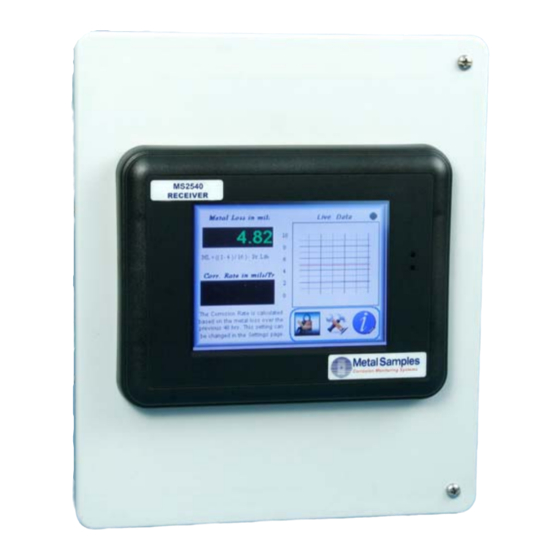
- Page 1 MS2540 Current Loop Receiver with RS485 Communication User Manual Metal Samples Company A Division of Alabama Specialty Products, Inc. 152 Metal Samples Rd., Munford, AL 36268 Phone: (256) 358‐4202 Fax: (256) 358‐4515 E‐mail: msc@alspi.com Internet: www.metalsamples.com ...
-
Page 3: Table Of Contents
SECTION 1 – INSTALLATION Shipping and Receiving ............................3 Mounting ................................4 Electrical ................................5 Physical Dimensions ............................6 Specifications ..............................7 Equipment Safety ............................... 9 SECTION 2 – START-UP AND OPERATION Receiver Start-Up ........................... 10 Operation ............................... 11 Controls Operation ..........................13 Title Screen ................................ -
Page 5: Section 1 - Installation
Upon receipt, equipment should be carefully inspected for transit damage. If damage is apparent, notify Metal Samples and the carrier for claims inspection. Unloading Open the package and remove the instrument carefully. The instrument contains a display screen. -
Page 6: Mounting
MOUNTING... -
Page 7: Electrical
ELECTRICAL Main Power Connection Connect Single Phase, 100- 240V AC, 50/60 Hz to the plug provided in the bottom of the unit. The maximum current requirement is 2 A. Note: In some cases, the instrument is shipped without a connector on the power cord. Each locality should inspect the power cord and install the proper connector if necessary. - Page 8 RS485 Connections 1. Connect ‘D +’ of the DCS / PLC to the TB2-1 (D+) terminal. 2. Connect ‘D -‘ of the DCS / PLC to the TB2-2 (D-) terminal. 3. Connect Signal Ground of the DCS / PLC to the TB2-3 (SG) terminal 4.
-
Page 9: Physical Dimensions
PHYSICAL DIMENSIONS 0.75”... -
Page 10: Specifications
SPECIFICATIONS Input Inputs: 4-20mA current loop from one ER or LPR corrosion transmitter Current Loop Source Voltage: 24 VDC Input Impedance: 250 ohms Maximum Current Loop Distance: 10,000 feet (3,048 meters) Output Outputs: RS-485 Modbus, Ethernet Display Type: Color touch screen Displayed Values: Metal Loss (mils or mm) or Corrosion Rate (mpy or mm/y) Resolution:... -
Page 11: Equipment Safety
EQUIPMENT SAFETY Always follow these warnings and safety procedures: Before attempting to operate or perform any service functions, all operators and service personnel should read this manual to become familiar with the complete operation of the equipment. Becoming familiar with all operating procedures will greatly reduce the possibility of accidents or injury. -
Page 12: Receiver Start-Up
(overnight, weekend, or holiday), follow the procedure below to start the equipment: Refer to ‘MS2540 Receiver Connection Details’ for detailed receiver connections to transmitter and DCS/PLC/PC. Ensure the transmitter connections are connected properly to the receiver unit. -
Page 13: Operation
OPERATION The MS2540 is a line powered current loop receiver that provides 24V DC to power a 2 wire 4- 20 mA instrument loop, and provides a display of the loop value in metal loss and calculated corrosion rate. The device can also be connected to the DCS/PLC/PC via RS485 Serial Communication. - Page 14 TABLE 1 : PROBE LIFE AND ELEMENT ID Element Element Probe Life Element Identifier Type Thickness 40 mil 10 mil WR 40 Wire Loop 80 mil 20 mil WR 80 4 mil 2 mil TU 04 Tube Loop 8 mil 4 mil TU 08 4 mil...
-
Page 15: Controls Operation
CONTROLS OPERATION TITLE SCREEN The Title screen is the first screen displayed when power is activated and after the equipment boots up. -
Page 16: Main Screen
MAIN SCREEN Metal Loss in mils Display indicates the active metal loss data in selected unit (mils/microns). Corr. Rate in Mils/Yr Display indicates the active Corrosion rate in selected unit (mils/microns) per year. The corrosion rate is calculated based on the metal loss over the previous hours. Timing is settable through the Settings page. - Page 17 Live Data This graph window displays the live data from the transmitter in metal loss value. Page Navigation Buttons Press ‘Setup’ image button to display the ER / LPR Setup page. Press ‘Status’ image button to display the Status page. Press ‘Chart’...
-
Page 18: Setup Screen
SETUP SCREEN Display Unit Press the ‘Display unit’ button to change the display units of the metal loss and corrosion rate as mils or microns on the main page. Calculation Period This selection unit is for calculating the corrosion rate per year based on the set time. This can be selectable as 48 hours, 7 days, 15 days and 30 days. - Page 19 Corr. Rate Display in Mils / Yr Display indicates the active corrosion rate in selected unit (mils/microns) per year. The corrosion rate is calculated based on the metal loss over the previous hours. Timing is settable through the Settings page. For the first time after the power is turned on or the probe is changed, the corrosion rate starts to calculate after 48 hours and displays the value even if the set value is other than 48 hours.
-
Page 20: Data Chart Screen
DATA CHART SCREEN Year Press the ‘Year’ entry box and enter the year for which the metal loss data needs to be displayed in the chart. Month Select the month to view the metal loss data for the respective month or select ‘ALL’ to view the data for the whole year. -
Page 21: Status Screen
STATUS SCREEN Receiver Status Power - The Power light becomes green when the receiver power supply is in good condition. - The Run light becomes green when the receiver is in run condition and the processor is acquiring the metal loss data. Comm. - Page 22 Modbus Data Registers Device Status (#40001) - The Modbus register data of the receiver status is displayed. Address (#40002) - Displays the receiver address. Baud Rate (#40003) - Displays the Baud Rate settings of the receiver. Metal loss (#40018) - Fault light becomes Red when a fault occurs with the receiver unit.
-
Page 23: Option Settings Screen
OPTION SETTINGS SCREEN Instrument Setting Follow the below steps to calibrate the receiver with respect to the transmitter current. 1. Turn off the receiver power and set the transmitter switches to 20mA. 2. Turn on the power. Port Settings Address Enter the address for receiver (1 to 32) Baud Rate Enter the numerals respective to the Baud Rate for the RS 485... -
Page 24: Calibration Screen
CALIBRATION SCREEN Calibration Procedure Follow the below steps to calibrate the receiver with respect to the transmitter current. 1. Turn off the receiver power and set the transmitter switches to 20mA. 2. Turn on the power. 3. Wait for a minute. 4. -
Page 25: Help Screen
HELP SCREEN Page Navigation Buttons Press ‘Home’ button to display the Main page. -
Page 26: Section 3 - Maintenance
3. MAINTENANCE GENERAL / PREVENTATIVE MAINTENANCE Only qualified service technicians should maintain and repair the equipment. Follow all local safety regulations while servicing. Every 12 Months - Check and tighten all electrical screw connections. FUSE REPLACEMENT Main Fuse Replacement (F1- 2A) The main fuse can be replaced by following the below mentioned procedure. - Page 27 Loop Current Fuse Replacement (F2 – 0.1A) 1) Turn off the main power switch. 2) Remove the loop current fuse holder cap by rotating the fuse holder cap towards the left. 3) Remove the glass fuse from the fuse holder. 4) Replace with the same type of fuse.
-
Page 28: Section 4- Troubleshooting
4. TROUBLESHOOTING Troubleshooting is the process of identifying a problem, finding the cause of the problem and performing the necessary steps to correct it. Fault messages display on the status window to identify the location and type of fault that has occurred.
Need help?
Do you have a question about the MS2540 and is the answer not in the manual?
Questions and answers