Table of Contents
Advertisement
Quick Links
Servo Trigger Hookup Guide
Introduction
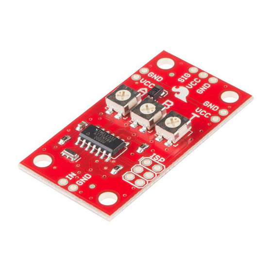
The Servo Trigger is a small board that helps you deploy hobby RC servo
motors. When an external switch or logic signal changes state, the Servo
Trigger tells an attached servo motor to move from position A to position B.
The Servo Trigger in action.
To use the Servo Trigger, you simply connect a hobby servo and a switch,
then use the onboard potentiometers to adjust the start/stop positions and
transition time. You can use a hobby servos in your projects without having
to do any programming!
In This Tutorial
This hookup guide starts with some background information about hobby
servo motors. From there, it jumps into getting the Servo Trigger working
with a small servo, then examines some of the inner workings. Finally, for
the adventurous, it explains how to customize the Servo Trigger by
reprogramming it.
Suggested Reading
• An Introduction to Motors.
• More information about hobby servo motors.
• Some background on Pulse Width Modulation.
Servo Motor Background
Page 1 of 14
Advertisement
Table of Contents

Related Manuals for sparkfun Servo Trigger


Summary of Contents for sparkfun Servo Trigger
- Page 1 Servo Trigger Hookup Guide Introduction The Servo Trigger is a small board that helps you deploy hobby RC servo motors. When an external switch or logic signal changes state, the Servo Trigger tells an attached servo motor to move from position A to position B.
-
Page 2: Electrical Connection
Page 2 of 14 In the most generic sense, a “servomechanism” (servo for short) is a device that uses feedback to achieve the desired result. Feedback control is used in many different disciplines, controlling parameters such as speed, position, and temperature. In the context we are discussing here, we are talking about hobby or radio- control servo motors. -
Page 3: Control Signal
It starts to feel sluggish just before it dies. If you’re not using batteries, the 5VDC available from a garden variety power supply is a good option. If you’re using the Servo Trigger to control your motor, the absolute maximum supply voltage that should be applied is 5.5 VDC. - Page 4 Page 4 of 14 Internally, the mechanism of a servo motor uses a potentiometer attached to the rotating shaft to sense the position. It measures the width of the incoming pulse, and applies current to the motor to turn the shaft correspondingly.
-
Page 5: Getting Started Quickly
We’ll explore some more specific use cases in the following sections. Getting Started Quickly Let’s jump in and build a circuit to show how the Servo Trigger works! Materials and Tools You’ll need to following materials to build this example circuit. - Page 6 Page 6 of 14 Switch Assembly Then prepare the power plug pigtail. Take a pair of wires, and strip the ends, then screw them to the power jack adapter – if you look closely at the adaptor, you’ll notice that there are a small embossed in the plastic.
-
Page 7: More Details
The heart of the Servo Trigger is an Atmel ATTiny84 microcontroller, running a small program that implements the servo control features we are discussing here. Just because the Servo Trigger saves you from needing to write code doesn’t mean that there’s no programming involved! The servo control signal is generated using a 16-bit hardware timer. - Page 8 Page 8 of 14 Configuration The Servo Trigger has a couple of configuration options. If you look at the back of the PCB, you’ll notice two solder jumpers that can be used to change Servo Trigger’s response. Configuration Jumpers, SJ1 and SJ2.
-
Page 9: Input Polarity
These currents can get surprisingly high as you add more motors to the system – you’ll need to select a power supply with adequate capacity. The Servo Trigger is designed to make it easy to daisy chain boards – you can simply connect the VCC and GND pads on adjacent boards. -
Page 10: Troubleshooting
Page 10 of 14 In applications where the motors are moving non-trivial loads, it’s a better bet to use heavier gauge wires and give each Servo Trigger a direct connection to the power supply. The configuration is commonly known as “star power.”... - Page 11 Page 11 of 14 The Servo Trigger was designed to make using servo motors easy, but it may not fit every application. You might need different timing, or different logic that interprets how the input is translated into the motor drive signal.
-
Page 12: Implementation Details
Page 12 of 14 The Servo Trigger comes with a couple of response modes that should be useful for most servo control needs, but in the case they’re not a good fit, they can be modified. There are several other modes hidden in the source file. In addition to the two default modes, there are three other modes. -
Page 13: Going Further
Here’s the bubble diagram for the bistable FSM. Building New State Machines In the Servo Trigger, a state machine is implemented as a single function, which contains a statement wherein each state is a . - Page 14 Page 14 of 14 • Wikipedia has a very detailed article about Finite State Machines. https://learn.sparkfun.com/tutorials/servo-trigger-hookup-guide?_ga=1.235617985.193945... 3/29/2016...
Need help?
Do you have a question about the Servo Trigger and is the answer not in the manual?
Questions and answers