Table of Contents
Advertisement
Quick Links
DESCRIPTION
Demonstration circuit 1937B is a supercapacitor charger
and backup controller with supercapacitor health and
system monitoring; featuring the
has a buck supercapacitor charger, backup boost controller
and an input ideal diode to disconnect the input supply
in backup mode. An output ideal diode allows the super-
capacitors to supply the output when VCAP is above the
set backup voltage. As the capacitor stack voltage drops
PERFORMANCE SUMMARY
PARAMETER
Input Supply Range
Input Current Limit
V
Backup Operating Voltage
OUT
V
Float Voltage
CAP
Max Charge Current
t
BACKUP
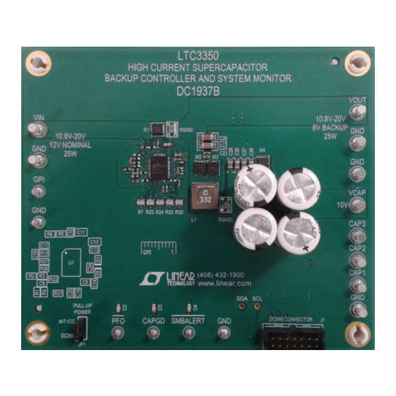
BOARD PHOTO
High Current Supercapacitor Backup
Controller and System Monitor
LTC
3350. The LTC3350
®
Specifications are at T
CONDITIONS
Boost Mode
Buck Mode
P
= 25W, I
BACKUP
BOOST
DEMO MANUAL DC1937B
down to the set output voltage, the LTC3350 will operate
as a boost regulator to supply the output until the energy
in the supercapacitors are depleted.
Design files for this circuit board are available at
http://www.linear.com/demo/DC1937B
L, LT, LTC, LTM, Linear Technology and the Linear logo are registered trademarks and
QuikEval is a trademark of Linear Technology Corporation. All other trademarks are the property
of their respective owners.
= 25°C
A
= 9.67A, 3 ≤ V
≤ 10
CAP
LTC3350EUHF
MIN
TYP
MAX
10.8
12
20
2
6
10
5.33
3.2
UNITS
V
A
V
V
A
s
dc1937bf
1
Advertisement
Table of Contents

Subscribe to Our Youtube Channel
Related Manuals for Linear Technology DC1937B

Summary of Contents for Linear Technology DC1937B
- Page 1 An output ideal diode allows the super- L, LT, LTC, LTM, Linear Technology and the Linear logo are registered trademarks and capacitors to supply the output when VCAP is above the QuikEval is a trademark of Linear Technology Corporation. All other trademarks are the property set backup voltage.
-
Page 2: Typical Application
5V position. 9. On the LTC3350 Control Window, click on the CAP 5. Set the JP1 jumper on the DC1937B board to the and ESR Measurement START button. An In Process DC590 position. indicator displays while the measurement is in process. - Page 3 VCAP and PFO. Set the oscilloscope to trigger on the falling edge of PFO. 14. The DC1937B can be modified to operate at differ- ent frequencies, operating voltages, input and boost 12. Remove the input power and observe how the output currents.
-
Page 4: Application Information
Figure 3. Charger Efficiency Figure 4. Boost Efficiency The DC1937B was designed to provide 25W of power for each capacitor in the stack at EOL can be calculated by a total of 1.8 seconds with a backup voltage of 6V. It was... - Page 5 (MAX) (STK(MAX) (MIN) (STK(MIN) LOSS for EOL. For the DC1937B, the NESSCAP ESHSR-0010C0- Where C is the total stack capacitance, V 002R7 was chosen with a C of 7F, an ESR of 64mΩ STK(MIN) based on the higher calculated V and a maximum current of 10.1A.
- Page 6 °C. VIEW LTC3350 PRODUCT PAGE button opens an Internet Register text boxes displays the associated register values browser and searches the Linear Technology Corporation in hexadecimal format. website for information on the LTC3350 when an Internet connection is available.
- Page 7 DEMO MANUAL DC1937B USING THE LTC3350 SOFTWARE Figure 5. LTC3350 Control Window VCAP FB text box allows the user to set the CAPFB refer- VSHUNT Write text box displays the value that will be or has ence voltage from 0.6375V to 1.2V in 37.5mV increments.
- Page 8 DEMO MANUAL DC1937B USING THE LTC3350 SOFTWARE Figure 6. Monitor Status/Alarms Tab MONITOR STATUS/ALARMS TAB Alarm Bits indicate when the associated alarm_reg register bits are set. See the data sheet from more information on The Monitor Status/Alarms tab contains the indicators for these bits.
- Page 9 DEMO MANUAL DC1937B USING THE LTC3350 SOFTWARE Figure 7. Set Alarms Tab SET ALARMS TAB CAP LO alarm text box allows the user to enter a capacitance based on the current ctl_cap_scale setting in the ctl_reg. A The Set Alarms tab contains text boxes to allow the user...
- Page 10 DEMO MANUAL DC1937B USING THE LTC3350 SOFTWARE Apply button writes to all of the alarm registers and reads VPFI Resistor Settings text boxes allow the user to enter the values back from the LTC3350. the PFI resistor divider network in kΩ. The calculated falling PFI threshold set point is displayed in Volts.
- Page 11 The standard ages below 1.8V. Increasing the resistance much above DC1937B board is set up for a 500mA maximum shunt 1kΩ can cause ADC measurement inaccuracies. The ITST current. This current can be increased by turning on exter- resistor must be increased to 1MΩ...
- Page 12 ITST _ EXT +ITST _EXT +I )• TIME 0.2V Figure 11. High Current Balancing/Shunting CALCULATING THE CAPACITANCE The calculation for the standard DC1937B is: • 336µF •MEAS _CAP STACK for large scale and • 3.36µF •MEAS _CAP STACK for small scale.
-
Page 13: Parts List
DEMO MANUAL DC1937B PARTS LIST ITEM REFERENCE PART DESCRIPTION MANUFACTURER/PART NUMBER Required Circuit Components C2-C5 CAP, ELECTRIC DOUBLE LAYER, 10F, 2.7V NESSCAP, ESHSR 0010C0 002R7 CAP, CHIP, COG, 120pF, ±5%, 25V, 0402 MURATA, GRM1555C1E121JA01D C10, C25 CAP, CHIP, X5R, 0.1µF, ±10%, 25V, 0402 TDK, C1005X5R1E104K050BC CAP, CHIP, X5R, 1µF, ±10%, 25V, 0603... - Page 14 DEMO MANUAL DC1937B PARTS LIST ITEM REFERENCE PART DESCRIPTION MANUFACTURER/PART NUMBER R1, R2 RES, CHIP, 20Ω, ±1%, 1/16W, 0402 VISHAY, CRCW040220R0FKED R10, R11 RES, CHIP, 0402 R15, R16, R18 RES, CHIP, 5.1kΩ, ±5%, 1/16W, 0402 VISHAY, CRCW04025K10JNED RES, CHIP, 1MΩ, ±5%, 1/16W, 0402...
-
Page 15: Schematic Diagram
Information furnished by Linear Technology Corporation is believed to be accurate and reliable. However, no responsibility is assumed for its use. Linear Technology Corporation makes no representa- tion that the interconnection of its circuits as described herein will not infringe on existing patent rights. - Page 16 Linear Technology Corporation (LTC) provides the enclosed product(s) under the following AS IS conditions: This demonstration board (DEMO BOARD) kit being sold or provided by Linear Technology is intended for use for ENGINEERING DEVELOPMENT OR EVALUATION PURPOSES ONLY and is not provided by LTC for commercial use. As such, the DEMO BOARD herein may not be complete in terms of required design-, marketing-, and/or manufacturing-related protective considerations, including but not limited to product safety measures typically found in finished commercial goods.
Need help?
Do you have a question about the DC1937B and is the answer not in the manual?
Questions and answers