Table of Contents
Advertisement
Quick Links
Advertisement
Table of Contents

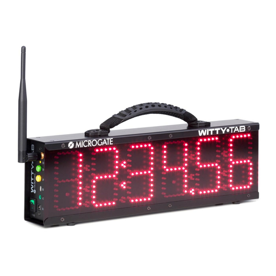
Summary of Contents for Microgate WITTI-TAB
- Page 1 User Manual Version 1.1...
-
Page 2: Table Of Contents
P12 – ReacTime ........................28 2.14 P13 – Countdown ....................... 28 2.15 P14 – Lap Time ........................29 2.16 P15 - Witty·SEM ......................... 29 2.17 P96 – Photocell Filter ......................29 Microgate Witty TAB User Manual Page 2 of 33... - Page 3 2.18 P97 - LED Segments Test ....................30 2.19 P98 - Photocell Radio Signal Test ..................30 2.20 P99 – Parameter Configuration ..................31 Microgate Witty TAB User Manual Page 3 of 33...
-
Page 4: Hardware
Radio transmission power 10 mW Radio transmission range Approx. 150 meters Processing unit 16-bit microcontroller Time base 12. quartz 8 MHz, stability ±10ppm between 0°C and +45°C Power supply Two internal Pb batteries Microgate Witty TAB User Manual Page 4 of 33... - Page 5 Buttons • LAP/RESET button • Type B MICRO USB connector to connect to a PC Connections • Jack connector for external input/output • SMA connector for connection to an external aerial Microgate Witty TAB User Manual Page 5 of 33...
-
Page 6: Control Panel
SUPPLY: Connector for external power supply and battery charging This button will hereafter be referred to as TART This button will hereafter be referred to as ESET Figure 2 – Control panel Microgate Witty TAB User Manual Page 6 of 33... -
Page 7: Power Supply And Battery Charging
(“START STOP” and “LAP RESET”) pressed The LED on the power adapter indicates the following statuses: STATUS STATUS LED on the POWER ADAPTER • Charging Yellow • Charged/maintenance Green Microgate Witty TAB User Manual Page 7 of 33... -
Page 8: Photocells
(or a similar reflecting surface) is found. To switch off the photocell press the button until the LED turns red, then release it. Microgate Witty TAB User Manual Page 8 of 33... -
Page 9: Mounting Photocells And Reflectors On Tripods
4 mounting directions with respect to the tripod). Mount the devices onto the top of the tripod inserting the front of the platform, and then the rear until the tab clicks into place. Microgate Witty TAB User Manual Page 9 of 33... -
Page 10: Statuses And Colors Of The Photocell Led
Green - Pause • Battery charged • Red - pause Battery empty Slave photocell (lower serial number) • Green fast blinking light Battery charged • Red fast blinking light Battery empty Microgate Witty TAB User Manual Page 10 of 33... -
Page 11: Paired Photocells
SLAVE. As the Master photocell transmits the signal to the timer, to ensure a wider aerial range, the latter should always be mounted on top. Master: Higher S/N, blinking at regular speed. Always on TOP! Slave: Lower S/N, blinking fast. Microgate Witty TAB User Manual Page 11 of 33... -
Page 12: Radio System
For excellent reception, position the Witty·TAB display board at a height of at least 50 cm (without it touching the ground) and do not place it on top of metal objects. START LAP1 LAPn STOP Wireless Radio Transmission Max 150 mt. Microgate Witty TAB User Manual Page 12 of 33... -
Page 13: Duration Of The Transmission Impulse (Radio Power)
Even if the distance is shorter, the second impulse will be detected anyway, as its "tail" will be longer than that of the previous one. STO Frame STA Frame Trasmission of STO for 1,2s Trasmission of STA for 1,2s Start Stop 0,8 sec (< 1.2) Microgate Witty TAB User Manual Page 13 of 33... - Page 14 Trasmission of L1 for 1,2s Trasmission of STO for 1,2s Trasmission of STA for 1,2s Trasmission of L2 for 1,2s Start Stop 0,8 sec (< 1.2) 0,6 sec (< 1.2) 0,5 sec (< 1.2) Microgate Witty TAB User Manual Page 14 of 33...
-
Page 15: Use Of The Display Board In Manual Mode
There is another sensor on the fourth digit, but only the one in the upper left corner is used for active control. The manual minimum/maximum brightness values range from 0 to 100% at 5% steps (see program Microgate Witty TAB User Manual Page 15 of 33... -
Page 16: Internal Programs
• Keep the YELLOW L button pressed for at least 3 seconds. ESET • The currently selected program is displayed. • Press the GREEN S button to scroll down the above-listed programs. TART Microgate Witty TAB User Manual Page 16 of 33... - Page 17 To change the parameters of a particular setting use the GREEN S button to increase TART digits one by one every time you press it, keep pressed to scroll ahead. When inputting 3-digit parameters (0-999), counter scrolling speed increases after 99. Microgate Witty TAB User Manual Page 17 of 33...
- Page 18 5 seconds, press the yellow L button. ESET No particular photocell configuration is needed (the first impulse is the start impulse, the second is the stop impulse). START STOP Microgate Witty TAB User Manual Page 18 of 33...
-
Page 19: P1 - Start, Lap1, Stop
2, S TART Similar to the previous but with the addition of two intermediate times. Both intermediate times and the final time are displayed for 5 seconds. START LAP1 LAP2 STOP Microgate Witty TAB User Manual Page 19 of 33... - Page 20 In the above-mentioned cases it is not necessary that the number of photocells be the same as that amount of intermediate times, one photocell used as start/stop/lap is enough. e.g. Lap time on an athletics track Microgate Witty TAB User Manual Page 20 of 33...
-
Page 21: P3 - Speed
Lap-Reset button is pressed. START STOP Mt.Cm. Please note: the P3 program expects the impulses to be coming from two different photocells, so for timing the lap speed use program P4. Microgate Witty TAB User Manual Page 21 of 33... -
Page 22: P4 - Lap Speed
When the display board receives the first impulse, it keeps displaying 0.00; after the second impulse it shows the calculated speed, displaying it until the next impulse is detected (second, third, nth lap) or the yellow Lap-Reset button is pressed. Microgate Witty TAB User Manual Page 22 of 33... -
Page 23: P5 - Start, Lapn, Stop
Insert the amount of SECONDS the final time is displayed (5-60) e.g. Three intermediate and waiting times of 10 seconds after arrival before resetting the timer P5 L 3 t 10 START LAP1 LAP... STOP Microgate Witty TAB User Manual Page 23 of 33... -
Page 24: P6 - Continuous Timing
__ Insert the amount of SECONDS of the dead time, during which no impulse is accepted (0-60) e.g. Three-seconds dead-time START Discarded LAP 1 LAP N STOP < T dead Microgate Witty TAB User Manual Page 24 of 33... -
Page 25: P7 - Starting System
In order to have homogeneous data for various athletes, it is advisable that they all start at the same distance from the first photocell, for instance applying an adhesive strip a few cm before it. Microgate Witty TAB User Manual... -
Page 26: P8 - Event Counter
To reset the counter press the yellow L button. ESET Examples of use: counting push-ups or "Go & Back" in a certain amount of time. How many in 1'00' ? Start Microgate Witty TAB User Manual Page 26 of 33... -
Page 27: P9 - Parallel Event Counter
In the example below first interrupt photocell A so that it is shown on the left (the display board changes from “-“ to “0”) and then photocell “B”; when both sides show “0” the test can begin. To reset both counters press the yellow L button. ESET Microgate Witty TAB User Manual Page 27 of 33... -
Page 28: P10 - Date And Time
In mode 1: Insert the duration of the countdown in the format hours:minutes:seconds The countdown starts with the green button S or by an external impulse (for example TART from a Witty·GATE) and can be reset by pressing L ESET Microgate Witty TAB User Manual Page 28 of 33... -
Page 29: P14 - Lap Time
• To enable the filter: Activate this program and register all allowed photocells by interrupting their light beam. The number on the display is showing the current number of registered photocells. Microgate Witty TAB User Manual Page 29 of 33... - Page 30 If the impulse is received, on the left side a counter is shown which increases with each impulse and on the right side the percentage indicating the signal power. To begin a new test press the yellow L button, in order to reset the counter and ESET percentage. Microgate Witty TAB User Manual Page 30 of 33...
- Page 31 (see below). (The Lynx ReacTime device must be programmed with the special firmware 1.51b05 and Witty·TAB is supporting this function starting from firmware version 1.00.05; Configuration ReacTime: Menu Training 12V Mode Pulse) Microgate Witty TAB User Manual Page 31 of 33...
- Page 32 On .. External reset enabled The external reset gets disabled automatically if the ReacTime function is active. When confirming the last settings using the yellow L button, the previously selected ESET program appears. Microgate Witty TAB User Manual Page 32 of 33...
- Page 33 Microgate, REI2, RaceTime2, and MiSpeaker are registered trademarks belonging to Microgate s.r.l. Windows is a registered mark of Microsoft Co. Microgate s.r.l. reserves the right to modify the products described in this document and/or in the relative manuals without notice.
Need help?
Do you have a question about the WITTI-TAB and is the answer not in the manual?
Questions and answers