Table of Contents
Advertisement
Advertisement
Table of Contents

Summary of Contents for AXXIOM Manufacturing, Inc. SCHMIDT AIRPREP ADS 250
- Page 1 AIRPREP AIR DRYER SYSTEM OPERATION AND MAINTENANCE MANUAL NOVEMBER 2007 SAVE THIS MANUAL AND MAKE AVAILABLE TO ALL USERS OF THIS EQUIPMENT! Manual Part Number 7200-230 IOM Manufacturing, Inc. 11927 S. Highway 6, Fresno, Texas 77545 800.231.2085 * 281.431.0581 * fax 281.431.1717...
- Page 2 WARNING Any person intending to operate this equipment or any person intending to be in the vicinity during its operation must receive proper training from his/her supervisor, employer and/or supplier. If this equipment is to be leased or rented, the supplier must assure that the lessee or renter has received proper training before the lessee or renter takes possession of the equipment.
- Page 3 Instructions for use of manual sections This manual contains information needed to operate and maintain your Airprep System. Read this entire operations and maintenance manual before using your Airprep System. Pay close attention to the Rules for Safer Operation (Section 1.0), and the Dangers, Warnings, and Cautions identified. The purpose of safety symbols and explanations are to alert you of the possible hazards and explain how to avoid them.
- Page 4 Warning Label Identification and Location Listed below are the warning labels and the corresponding hazards encountered with this equipment. Refer to Figures 0.1(a) and 0.1(b) for images of the warning decals. Refer to Figures 0.2(a), 0.2(b) and 0.2(c) for the locations of these warning decals. Description Qty.
- Page 5 5) 7031-017 6) 7031-018 7) 7031-057 Figure 0.1(b) – Warning decal summary (continued) Figure 0.2(a) –Warning decal location for ADS 250 Dryer...
- Page 6 Figure 0.2(b) –Warning decal location for ADS 400-2500 Dryer Figure 0.2(b) –Warning decal location for ADS 3500 Dryer...
-
Page 7: Table Of Contents
Table of Contents Section Page Warning Decal Identification and Location Rules for Safer Operation Specifications and General Information System Requirements Abrasive Blast System General Operation AirPrep System General Operation Pre-operation Procedures Operating Instructions Maintenance and Inspection Instructions Drawings and Parts Lists 10.0 Recommended Spare Parts List 11.0... -
Page 8: Rules For Safer Operation
Rules for Safer Operation 1.1. GENERAL RULE FOR SAFER OPERATION. SCHMIDT® AIRPREP SYSTEMS HAVE BEEN DESIGNED TO BE SAFE WHEN USED IN THE PROPER MANNER. ALL AIRPREP SYSTEMS ARE POTENTIALLY DANGEROUS IF ALL SAFETY PRECAUTIONS ARE NOT RIGOROUSLY FOLLOWED. PROPER TRAINING IS REQUIRED BEFORE OPERATION. - Page 9 1.5. PROTECT YOUR EYES. Do Not operate this equipment without wearing OSHA approved safety glasses. Observe all applicable local, state and federal safety regulations. See Section 3.9 and OSHA 29 CFR 1910.133. The abrasive blast operation produces a dusty work environment which can leave dust that can be blown in the face and eyes of operators.
- Page 10 1.8. PROTECT YOUR HEARING. Do Not operate this equipment without wearing OSHA approved hearing protection. Observe all applicable local, state and federal safety regulations. See Section 3.9 and refer to OSHA 29 CFR 1910.95. Loud noise is generated by the blast nozzle and the blowdown operation of this equipment. Wear OSHA approved hearing protection.
- Page 11 1.17. AVOID DANGEROUS ENVIRONMENTS. Do Not operate this equipment in elevated areas without using fall protection equipment. Certain applications of this equipment may require the use of scaffolding. Use of scaffolding creates hazardous situations such as tripping and fall hazards which can result in serious injury or death to operating personnel.
- Page 12 Do Not operate this equipment if the ASME pressure vessel nameplate is missing. Contact Axxiom Manufacturing, Inc. for technical support. 1.26. DO NOT MODIFY VESSEL. Do Not modify or alter this equipment, or any blast equipment, or controls thereof without written consent from Axxiom Manufacturing, Inc.
- Page 13 Do Not sell, rent, or operate abrasive blasters without remote controls. OSHA regulations require remote controls on all abrasive blasters. All abrasive blasters must be equipped with automatic (deadman) type remote controls (either pneumatic or electric). Failure to use remote controls can cause serious injury or death to the operator(s) or other personnel in the blasting area.
- Page 14 accidental start up and result in injury to personnel. 1.40. NEVER USE ABRASIVE NOT INTENDED FOR BLAST EQUIPMENT. Do Not use abrasive blast media containing free silica. Silica can cause silicosis or other related respiratory damage. Verify that the abrasive is intended for use in blasting equipment. Personal protective equipment, including airline filters and respirators, must be used for all abrasive blasting operations.
-
Page 15: Specifications And General Information
burnout. Before starting the motor, follow manufacturer’s recommendations. Turn the fan by hand to eliminate possible motor burnout in the event the fan has been damaged in shipment. Observe operation after the motor has been started for the first time. 1.51. - Page 16 2.1.1. Verify that the operation and maintenance manual is included with the Airprep System when it is received. Verify that the operation and maintenance manual is included with the Airprep System when it is delivered to the purchaser. 2.1.2. This equipment is intended for knowledgeable and experienced users. No person or persons should be allowed to operate this equipment without first receiving proper training in the use of this equipment.
-
Page 17: System Requirements
2.4.2. In order to maintain the high level of quality and quality control used in the manufacture of this vessel, it is required that any and all welded repairs to this vessel be performed by a reputable shop holding a National Board “R” Stamp and/or an ASME “U” stamp, depending on state or city law. - Page 18 Blast nozzle The primary air consumption in a blast system is by the blast nozzle. This usage can vary greatly depending upon the number of blast outlets, nozzle size of each outlet, and the blast pressure. The nozzle consumption and other usages must be evaluated for maximum operating efficiency of the AirPrep System.
- Page 19 purchase however, the motor can be rewired at installation. If the unit is to be rewired it may be necessary to change the motor starter and/or the thermal overload strips. Only a qualified electrician should install and/or make electrical changes to the AirPrep Systems. Power connections to AirPrep System with electric motors expose operators to high electrical voltages.
-
Page 20: Abrasive Blast System General Operation
Occupational Health and Safety Administration (OSHA) requires the employer to assess the workplace to determine what PPE is necessary and supplied to each operator (Reference 29 CFR 1910 Subpart I). OSHA requires that this equipment meet or be equivalent to standards developed by the American National Standards Institute (ANSI). -
Page 21: Airprep System General Operation
supplied air from an air compressor which will then supply air to the blast nozzle. The abrasive blast stream through the blast nozzle is used for removing rust, paint, or other unwanted surface defects. After abrasive blasting, the surface is ready for new paint or coating. The AirPrep System is one of a group of components used in an abrasive blasting job. - Page 22 equipment. The system removes moisture and contaminants that shorten the life of equipment controls and decrease blasting efficiency. Compressed air enters the AirPrep System at the pre-filter (#4) which filters trash and condensed moisture from the incoming air. The air flow then enters the aftercooler radiator (#8) where the flow is passed through a heat exchanger.
- Page 23 Valve, fitting, and/or hose rupture can cause serious injury or death. Do Not install or connect any valves, fittings or hoses that are not rated for a minimum 150 psi operating pressure. Pre-filter Compressed air enters the system through the air inlet pre-filter (#4) (the maximum inlet pressure should not exceed 150 psi).
- Page 24 Failure to lubricate the air motor will result in motor failure. Electric Motor (radiator fan) Electric aftercooler fan motors (#9) are optional and are available with a 115/208-230 vac 1 ph, 208-230/460 vac 3 ph, 230 vac 1 ph, or 230/460 vac 3 ph rating depending on the size of the aftercooler.
- Page 25 The Air Prep System is a Pressurized Vessel. Propelled objects will cause serious injury or death. Depressurize vessel before performing any maintenance. See Section 6.2. Figure 5.1 – Typical AirPrep Dryer System 5.11 Depressurize (Blowdown) The drain ball valve (#19) is used to release all the compressed air (depressurize) from inside the AirPrep System separator tank (#20).
-
Page 26: Pre-Operation Procedures
5.13 AirPrep System Air Outlets The AirPrep System air outlets are located on the after-filter (#5). There are (3) three outlet ports, (1) one the same size as the aftercooler piping size and (2) two 1" auxiliary ports (see Section 2.7). The ADS 250 has only (1) one 1-1/4" air outlet. There are no fittings or ball valves provided with the outlets. - Page 27 The AirPrep System is a pressurized vessel. Propelled objects will cause serious injury or death. Depressurize vessel before performing any maintenance. See Section 6.2. This section contains part identification numbers (#) within the text that are found on the Figure 6.1. Refer to these drawings as needed while reading this manual.
- Page 28 Figure 6.1 – Typical AirPrep Dryer System 6.1.5. Units having electric aftercooler fan motors must be installed by qualified personnel. Follow manufacturer’s recommendations.
- Page 29 Power connections to AirPrep System with electric motors expose operators to high electrical voltages. Contact with high electrical voltages can result in serious injury or death. Only qualified personnel should install or perform maintenance on the electrical system. 6.1.6. Open drain valves (#7) on the pre-filter (#4) and after-filter (#5), petcock valve (#22) (units with air motor) and drain valve (#19) on the separator tank to drain out moisture inside.
- Page 30 The air compressor ball valve is not part of the AirPrep System and is not provided with the unit. It is the responsibility of the user to verify that an air compressor outlet ball valve is installed so the air pressure can be isolated from the AirPrep System. 6.2.2.
- Page 31 THIS PAGE INTENTIONALLY BLANK Handway Cover Installation Procedures (See Figure 6.3(a)) 6.3.1. Check that the handway cover, crab, bolt, and gasket are dimensionally correct for the size handway weld ring of the pressure vessel.
- Page 32 a) Measure and write down the inside dimensions “A” and “B” of the handway weld ring. See Figure 6.3(a). b) Verify the size of the handway assembly by comparing the weld ring measurements from step “a” to the dimensions shown in Table 6.3(c). c) Verify that the dimensions of the cover, crabs, bolts, and gasket match the corresponding dimensions given in Table 6.3(c).
- Page 33 Figure 6.3 (a) – Handway Assembly Figure 6.3 (b) – Handway Components 6” x 8” Handway Dimensions Component Weld Ring 6-5/8” 8-1/2” Handway Cover 7-11/16” 9-7/8” Handway Gasket 7-3/4” 9-3/4” Handway Crab 2-3/8” 8-3/4” Square Head Bolt 3/4”-10 UNC 4-1/2” Table 6.3 (c) –...
-
Page 34: Operating Instructions
Operating Instructions Filling The AirPrep Air Dryer System With Deliquescent/Desiccant 7.1.1. The AirPrep System must be completely depressurized before filling can begin. Follow the depressurizing procedure in Section 6.2. Airborne particles and loud noise hazards from blowdown exhaust air can cause serious injury and loss of hearing. - Page 35 Figure 7.1 – Typical AirPrep Dryer System AirPrep System Startup 7.2.1. The AirPrep System must be properly prepared and all operating personnel must be thoroughly trained before beginning operation. Completely read and understand all sections of this manual before beginning operation. See the pre-operation procedures given in Section 6.0.
- Page 36 Figure 5.1 – Typical AirPrep Dryer System AirPrep System Shutdown 7.3.1 Close the aftercooler motor air supply valve (#21). On electric units press the “Stop” button on the motor starter control box to end cooling fan operation. 7.3.2 Close all the AirPrep System air outlet ball valves (see Figure 6.2). 7.3.3 Turn of the air compressor and/or close the compressor’s outlet valve (see Figure 6.2).
-
Page 37: Maintenance And Inspection Instructions
Maintenance and Inspection Instructions The AirPrep System is a Pressurized Vessel. Propelled objects will cause serious injury or death. Depressurize vessel before performing any maintenance. See Section 6.2. 8.1. The ASME Code is a standard covering materials, design, fabrication, and installation. Vessel integrity subsequent to purchase is the responsibility of the owner and/or user. - Page 38 8.5.3 Internal Cleaning Once a year disconnect piping and circulate a degreasing agent through the unit to remove sludge from the internal tubes. This will return the unit to full operating capacity. A thorough cleaning of the entire system in the same manner is desirable to avoid carry- over from unclean piping.
- Page 39 or leakage. Repair or replace any hoses or wires that show any signs of wear, leakage or other damage. Damaged wires and/or hoses can cause system malfunctions and can result in serious injury or death to operating personnel. Worn hose assemblies can rupture during operation and can cause serious personal injury. 8.8.
- Page 40 AIRPREP AIR DRYER SYSTEM MAINTENANCE SCHEDULE MAINTENANCE ITEM DAILY WEEKLY MONTHLY QUARTERLY REQUIRED Blaster Hydrostatic Test As required by state law and/or local authorities Vessel See Section 8.1 Check for exterior damage Blaster (corrosion, dents, bulges). Vessel See Section 8.2 Check for interior damage Blaster (corrosion / pitting).
-
Page 41: Drawings And Parts Lists
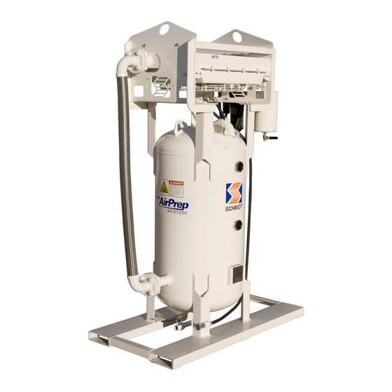
Drawings and Parts Lists The following pages contain drawings representing typical blast control systems and components. Determine the type of control system the abrasive blast system is equipped with (pneumatic or electric controls) then reference the appropriate drawing and parts list to determine the required parts. - Page 44 PARTS LIST (ADS 250) This section contains a parts breakdown covering all the major components which may require maintenance during operation of the AIR DRYER SYSTEM. The major items identified in the parts list are found on the drawings in Section 9.1 and 9.2. Refer to these drawings as needed while reading this manual.
- Page 45 PARTS LIST (ADS 400) This section contains a parts breakdown covering all the major components which may require maintenance during operation of the AIR DRYER SYSTEM. The major items identified in the parts list are found on the drawings in Section 9.1 and 9.2. Refer to these drawings as needed while reading this manual.
- Page 46 maintenance during operation of the AIR DRYER SYSTEM. The major items identified in the parts list are found on the drawings in Section 9.1 and 9.2. Refer to these drawings as needed while reading this manual. In addition, repair kits to rebuild these items are identified, and drawings are provided to aid in disassembly and installation of new parts (if applicable).
- Page 47 are found on the drawings in Section 9.1 and 9.2. Refer to these drawings as needed while reading this manual. In addition, repair kits to rebuild these items are identified, and drawings are provided to aid in disassembly and installation of new parts (if applicable). AIR DRYER 950 CFM (Part number: 1310-091 / 1310-092) ITEM PART NUMBER...
- Page 48 disassembly and installation of new parts (if applicable). AIR DRYER 1200 CFM (Part number: 1310-121 / 1310-122) ITEM PART NUMBER DESCRIPTION 3029-011-99 Nipple, 3" x close 7003-011 Flange, threaded 150 psi 3" 7003-011-01 Flange gasket, 3" 7003-011-02 Stud w/ nuts, 5/8" x 3-3/4" 1200-999-39 Moisture trap, 1200 inlet 1200-999-59...
- Page 49 AIR DRYER 1600 CFM (Part number: 1310-161 / 1310-162) ITEM PART NUMBER DESCRIPTION 3029-011-99 Nipple, 3" x close 7003-011 Flange, threaded 150 psi 3" 7003-011-01 Flange gasket, 3" 7003-011-02 Stud w/ nuts, 5/8" x 3-3/4" 1200-999-43 Moisture trap, 1600 inlet 1200-999-42 Moisture trap, 1600 outlet 3026-008-02...
- Page 50 ITEM PART NUMBER DESCRIPTION 3029-013-99 Nipple, 4" x close 7003-013 Flange, threaded 150 psi 4" 7003-013-01 Flange gasket, 4" 7003-013-02 Stud w/ nuts, 5/8" x 4" 1200-999-85 Moisture trap, 3500 inlet 1200-999-86 Moisture trap, 3500 outlet 3026-008-02 Bushing, 1-1/2" x 1/4" 3031-312-02 Hex nipple, 1/4"...
-
Page 52: Recommended Spare Parts List
10.0 Recommended Spare Parts Lists A) Pneumatic and Electric Fan Motor Systems (see note below & see Section 9.0 drawings) ITEM PART # DESCRIPTION 2401-502 Pre-Filter/After-Filter Drain Ball Valve, 1/4" full port 1300-XXX-12 Fan Assembly 1300-XXX-14 Fan Mount Bushing (only required for systems larger than ADS 750) 7000-001-06 Handway Gasket, 6”... -
Page 53: Airprep System Technical Data And Troubleshooting
11.0 AirPrep System Technical Data and Troubleshooting 11.1 TABLE 1 CAPACITY SELECTION CHART (MAX SCFM @ APPROACH) INLET TEMP F APPROACH TEMP F ADS 250 ADS 400 890 1025 308 ADS 750 871 1178 1360 415 754 1020 1180 390 950 1100 320 ADS 950 AIR DRYER... -
Page 54: Warranty And Reference Information
12.0 Warranty and Reference Information 12.1 Warranty The following sections are to be used as a guide in determining warranty policies and procedures for SCHMIDT® products. It is to be used in determining whether a warranty is justified and as a procedural guide in completing a SCHMIDT warranty claim. - Page 55 9. Axxiom Manufacturing, Inc. reserves the right to make product changes or improvements without prior notice and without imposing any obligation upon itself to install the same on its products previously sold. 10. The above warranty conditions can only be altered by Axxiom Manufacturing, Inc. Axxiom must confirm alterations in writing for each specific transaction.
- Page 56 Axxiom Manufacturing, Inc This equipment and all Schmidt® equipment are manufactured exclusively by Axxiom Manufacturing, Inc. If any operational or safety related questions arise relating to this equipment contact Axxiom Manufacturing, Inc. Phone: 1-800-231-2085 Website: www.axxiommfg.com Axxiom Manufacturing, Inc. 11927 South Highway 6 Fresno, Texas 77459 Occupational Safety and Health Administration (OSHA) establishes and enforces regulations regarding safety practices in the workplace including the abrasive blasting industry.
- Page 57 The Society for Protective Coatings (SSPC) consists of research and testing committees, conducts seminars and establishes industry standards on surface preparation methods, abrasive and coatings. Phone: 1-412-281-2331 Website: www.sspc.org The Society for Protective Coatings 40 24th Street Pittsburg, PA 15222-4643 National Association of Corrosion Engineers (NACE) develops test methods and recommended practices on surface preparation techniques and coatings.
- Page 58 13.0 Blasting Data 13.1 Table 1 Approximate Air Consumption (cfm) Per Blast Nozzle NOZZLE PRESSURE NOZZLE SIZE 60 psi 70 psi 80 psi 90 psi 100 psi 120 psi 140 psi No.2 1/8" No.3 3/16" No.4 1/4" No.5 5/16" No.6 3/8"...
Need help?
Do you have a question about the SCHMIDT AIRPREP ADS 250 and is the answer not in the manual?
Questions and answers