
Related Manuals for AMO Catalys OptiMedica

Summary of Contents for AMO Catalys OptiMedica
- Page 1 Operator Manual Part Number: 0160-6411, Rev A, 02/2019 Page 1 of 314 Software Release: cOS 5.00...
- Page 2 This page was intentionally left blank. Page 2 of 314 Part Number: 0160-6411, Rev A, 02/2019 Software Release: cOS 5.00...
- Page 3 CATALYS, OPTIMEDICA, INTEGRAL GUIDANCE, and LIQUID OPTICS are trademarks of AMO Manufacturing USA, LLC. All other trademarks are the intellectual property of their respective owners.
- Page 4 This page was intentionally left blank. Page 4 of 314 Part Number: 0160-6411, Rev A, 02/2019 Software Release: cOS 5.00...
-
Page 5: Table Of Contents
Table of Contents Indications for Use, Contraindications, Warnings, and Precautions.. 11 Indications for Use ....................11 Contraindications ....................11 Warnings......................11 Precautions ......................13 Adverse Effects....................16 User Training and Certification ................17 Target Patient Profile ..................18 Target Operator Profile ..................18 Physician........................ - Page 6 Table of Contents Network Cabling....................38 Setting Up Network Printing and Remote Connectivity (optional) ......38 Moving the System....................38 System Basics ...................... 39 Starting Up the System..................... 39 Logging Into the System ................... 40 Enabling the System ....................41 Verifying System Alignment ..................
- Page 7 Table of Contents Cataract Incisions Sideport(s) Geometric Details Screen ........ 110 Cataract Incisions Primary Laser Details Screen..........112 Cataract Incisions Sideport(s) Laser Details Screen......... 113 Treatment Plan Summary Screen................115 Editing the Treatment Plan ................115 Surgical Timeout Screen ..................116 Docking Screen....................
- Page 8 Table of Contents Intraoperative Instructions................175 Installing the LIQUID OPTICS™ Interface Components .......... 175 Scanning the Treatment Activation Label ............176 Installing the Disposable Lens ................. 177 Installing the Fluid Reservoir................178 Positioning the Patient ................... 179 Connecting the Mobile Patient Bed to the CATALYS® System....... 181 Homing the Mobile Patient Bed................
- Page 9 Table of Contents Safety and Regulatory ..............221 General Safety and Regulatory Information............221 Ocular Protection ....................222 Laser Safety Eyewear....................222 Normal System Operation................222 System Alignment Verification................ 222 Definitions from ANSI Z136.1-2007..............223 Electrical Hazards ....................224 Fire Hazards ...................... 224 Protecting Non-target Tissues ................
- Page 10 Table of Contents This page was intentionally left blank. Page 10 of 314 Part Number: 0160-6411, Rev A, 02/2019 Software Release: cOS 5.00...
-
Page 11: Indications For Use, Contraindications, Warnings, And Precautions
1 Indications for Use, Contraindications, Warnings, and Precautions This chapter contains the following major sections: • 1.1 Indications for Use, page • Contraindications, page • Warnings, page • Precautions, page • 1.5 Adverse Effects, page • 1.6 User Training and Certification, page •... - Page 12 Indications for Use, Contraindications, Warnings, and Precautions • Installation, maintenance, and repair should be performed only by OPTIMEDICA-certified personnel per the manufacturer’s recommendation and institutional standards. • Routinely inspect the system components for obvious signs of damage. Do not operate the laser if any of the components are damaged or if the cords are faulty or frayed.
-
Page 13: Precautions
Indications for Use, Contraindications, Warnings, and Precautions Purposeful misuse of custom fit adjustments to ocular surface(s) can result in patient injury and complication(s) and therefore must be avoided. • If a laser capsulotomy is interrupted, the system will not allow you to re-initiate the capsulotomy, as precise co-registration with the initial capsulotomy cannot be assured. - Page 14 Indications for Use, Contraindications, Warnings, and Precautions and may require service by OPTIMEDICA personnel. If the control panel remains blank for an extended period of time during system start-up, press the Power button on the front of the control panel to turn on the control panel. If the control panel remains blank, turn off the system with the key, wait at least one minute, and then restart the system.
- Page 15 Indications for Use, Contraindications, Warnings, and Precautions • After removal of the capsulotomy disc, if any capsulotomy thread remnant (less than 50 μm nominal thickness) is seen, do not remove it. Removal of a capsulotomy thread remnant could potentially cause or contribute to an anterior capsule tear and/or a non- circular, irregularly-shaped capsulotomy.
-
Page 16: Adverse Effects
Indications for Use, Contraindications, Warnings, and Precautions the installation site IT administrator to identify, analyze, evaluate, and control these risks. Subsequent changes to the installation site network could introduce new risks due to: ─ Changes to the network configuration ─ Connection of additional devices to the network ─... -
Page 17: User Training And Certification
Indications for Use, Contraindications, Warnings, and Precautions 1.6 User Training and Certification All users are required to participate in training provided by OPTIMEDICA personnel prior to treating patients with the CATALYS® Precision Laser System. Training will be tailored for the surgeon(s) and support staff and will consist of lectures and hands-on experience with the equipment. -
Page 18: Target Patient Profile
Indications for Use, Contraindications, Warnings, and Precautions b. Specifications and operation c. Emergency shutdown d. Maintenance 7. Review of the clinical trial results – text and iPad presentation 8. Indications for use, contraindications, warnings, and precautions The hands-on training includes but is not limited to: a. -
Page 19: Physician
Indications for Use, Contraindications, Warnings, and Precautions Physician • Education: Board-certified ophthalmologist • Knowledge and experience: ─ Experienced in performing cataract surgery ─ Fully trained in the use of the device • Permissible impairments: ─ Vision: Mildly impaired but corrected to 20/30 ─... - Page 20 Indications for Use, Contraindications, Warnings, and Precautions This page was intentionally left blank. Page 20 of 314 Part Number: 0160-6411, Rev A, 02/2019 Software Release: cOS 5.00...
-
Page 21: System Overview
2 System Overview This chapter contains the following major sections: • Introduction, page • 2.2 CATALYS® System Components, page • 2.3 Bench Testing, page • 2.4 Animal and Cadaver Testing, page • 2.5 Clinical Summary, page • 2.6 System Specifications, page •... -
Page 22: Catalys® System Components
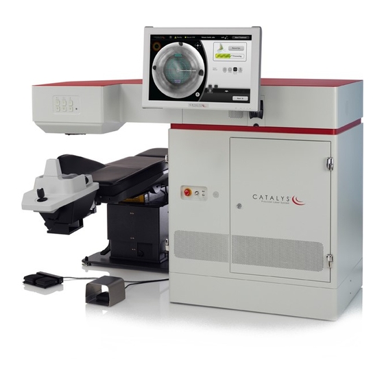
Chapter 2 System Overview may access the controls while they observe the patient and dock the LIQUID OPTICS™ Interface with the patient's eye that will receive surgery. The patient is now ready for treatment. To perform treatment, the doctor will sit within reach of the emergency laser stop button and other controls while viewing the display and will follow the prompts to confirm or adjust the treatment settings and perform the procedure. - Page 23 Chapter 2 System Overview Figure 2.1 CATALYS® System Components Laser Emission Indicator Docking Control Keypad LIQUID OPTICS™ Interface Touchscreen Control Panel - Vacuum Connections Graphical User Interface (GUI) On System Rear Panel: Network, Video Output, Footswitch, Door Interlock, Mobile Patient Bed and AC Power Connections with Headrest Emergency Laser Stop...
-
Page 24: Touchscreen Control Panel-Graphical User Interface (Gui)
Chapter 2 System Overview Touchscreen Control Panel—Graphical User Interface (GUI) The main control panel is located to the right of the physician. The control panel is user- adjustable and can be tilted and rotated to optimize viewing and access to controls. The control panel is a liquid crystal display (LCD) touchscreen, with controls for setting up system preferences and selecting treatment parameters. -
Page 25: Liquid Optics™ Interface Circular Label Reader
Chapter 2 System Overview LIQUID OPTICS™ Interface Circular Label Reader The LIQUID OPTICS™ Interface circular label reader reads data from the circular label on the LIQUID OPTICS™ Interface packaging and transfers it to the CATALYS® System software for identification and tracking purposes. The circular label must be held flat against the label reader on the left side of the system. -
Page 26: Emergency Laser Stop Button
Chapter 2 System Overview Figure 2.4 CATALYS® System and Mobile Patient Bed with Physician, Patient, and Technician For a complete description of the Mobile Patient Bed, including detailed instructions for use, refer to Appendix A – Mobile Patient Bed Instructions on page 233. -
Page 27: Key Switch
Chapter 2 System Overview Key Switch The system is equipped with a three-position key switch that enables the laser and its controls. In the Standby position, the key can be removed and the system is inactive. The Ready position enables power to the rest of the system. The switch is “momentary” when in the start position. The key is not removable when switched to either the ready or start position. -
Page 28: Door Interlock Connector
Chapter 2 System Overview Door Interlock Connector The external door interlock is a safety feature that disables laser and OCT emission if the treatment room doors are opened or the interlock connector is removed. Use of an external door interlock is optional; however, the door interlock connector must be inserted into the door interlock receptacle on the rear of the system whether or not the external door interlock feature is used. -
Page 29: Video Subsystem
Chapter 2 System Overview System processing cannot detect the posterior lens surface and the patient’s lens thickness is not known, the system can default to a conservative lens thickness value of 2.5 mm. Importantly, the system-integrated INTEGRAL GUIDANCE System processing ensures that adequate safety margins with respect to iris, lens capsule, and cornea are maintained regardless of eye morphology, orientation, or tilt, thus assuring safe delivery of the treatment laser pulses. -
Page 30: Bench Testing
Chapter 2 System Overview 2.3 Bench Testing Bench testing of the CATALYS® System was conducted to demonstrate the OCT sub-system's ability to measure depth, surface profiles and iris diameters with accuracy and precision. Various test article substrates of known dimensions were measured multiple times by the system's OCT sub-system. -
Page 31: Clinical Summary
Chapter 2 System Overview the minimum horizontal and vertical spot spacing coupled with maximum pulse energy. All laser- created corneal incisions met the histological acceptance criteria when compared to manual surgical incisions histology. Cadaver eye testing was also conducted to demonstrate qualitatively the intended laser incisions can effectively cut a verity of tissue types. - Page 32 Chapter 2 System Overview Table 2.2 Cumulative Dissipated Energy (CDE) Values Cumulative Dissipated Energy (CDE) CATALYS® System Control Mean 10.39 18.54 Standard Deviation 6.61 12.07 Minimum 0.91 5.23 Maximum 27.65 47.86 Safety of the CATALYS® System was evaluated by tallying all subject complications and adverse events and comparing these findings to those of the surgical Control cohort.
-
Page 33: System Specifications
Chapter 2 System Overview 2.6 System Specifications Treatment Laser Type Diode pumped solid-state, mode-locked Center wavelength 1030 nm (± 5 nm) Pulse energy 1 - 10 µJ Pulse duration < 600 fs Pulse rep. rate 120 kHz ± 5%, with integer down sampling when modulated CDRH laser class (21 CFR 1040) Class 4 Optical... -
Page 34: System Installation And Setup
Chapter 2 System Overview Environmental Requirements (Non-operating) Maximum altitude Standard commercial shipping altitude Temperature range 14 – 131°F (-10 – 55°C) Maximum humidity Up to 80% @ 131°F (55°C) non-condensing Physical Characteristics Height 1.15 m ± 0.025 m Length 1.64 m ± 0.025 m Width 0.87 m ±... -
Page 35: Connecting The System Components
Chapter 2 System Overview (± 3.6 °F) during a 45-minute period, the system will shut down. If the temperature of the installation environment goes below 15 °C or above 32 °C at any time, the system will shut down. The system should be positioned such that the treatment beam is aimed away from any windows or doors. -
Page 36: Connecting To An Ncast Telepresenter Video Recording System (Optional)
Chapter 2 System Overview Figure 2.8 System Rear Panel Connections Video Output Cable Receptacle, HDMI RJ45 Network Main Power or Display Port Door Interlock Receptacle Receptacle Receptacle (HDMI shown) and Connector Laser Footswitch Vacuum Footswitch Main System Receptacle Receptacle Circuit Breaker 3. -
Page 37: Connecting To A Network (Optional)
Chapter 2 System Overview Connecting to a Network (optional) The CATALYS® System is equipped with an RJ45 network connection on the system rear panel. Connecting the CATALYS® System to a network allows for: • Network printing of treatment reports • Remote system access by OPTIMEDICA Service Personnel to view system performance logs and perform system diagnostics OPTIMEDICA shall make available detailed instructions for implementing the optional network connection, upon written request by any appointed Medical-IT Risk Manager. -
Page 38: Network Ports
Chapter 2 System Overview Network Ports The CATALYS® System is equipped with a single RJ45 Ethernet connection in the system rear panel. The Ethernet port conforms to the minimum requirements of: • Ethernet standard 802.3u - 100BASE-TX, 100BASE-T4, 100BASE-FX • Fast Ethernet at 100 Mbps (12.5 Mbps) with auto-negotiation The Ethernet port to which the CATALYS®... -
Page 39: System Basics
Chapter 2 System Overview trained OPTIMEDICA personnel will re-install and test the system to ensure that it is operating within specification. 2.8 System Basics Starting Up the System 1. Verify that the system components are properly connected and that the main power cable is connected to an appropriate wall power outlet, as described in Connecting the System Components... -
Page 40: Logging Into The System
Chapter 2 System Overview Logging Into the System Enter your user name and password on the Login Screen, and then press the LOGIN button to log into the CATALYS® System. If you cannot remember your user name or password, press the CAN’T ACCESS ACCOUNT? button to submit a request to your CATALYS®... -
Page 41: Enabling The System
Chapter 2 System Overview Enabling the System The CATALYS® System has two operating states: • Control panel enabled; system and laser disabled • Control panel, system, and laser enabled Only the control panel is enabled at system start-up. You can add new treatment plans and edit previously added treatment plans with only the control panel enabled. -
Page 42: Verifying System Alignment
Chapter 2 System Overview One of the following laser status icons displays at the top of each screen to alert you to the laser status: Table 2.3 Laser Status Icons Asleep Laser is disabled/asleep; no laser energy is available Waking Laser is powering up;... - Page 43 Chapter 2 System Overview To verify the system alignment: 1. From the Home Screen or the Administrator Home Screen, press the VERIFY ALIGNMENT button to go to the Verify Alignment Screen. Figure 2.13 Verify Alignment Screen 2. As instructed on the screen, prepare the LIQUID OPTICS™ Interface and a new plastic test hemisphere for docking.
- Page 44 Chapter 2 System Overview 5. When the system detects that the disposable lens has been properly installed, the Vacuum panel opens. As instructed in the Vacuum panel, place and center the suction ring of the LIQUID OPTICS™ Interface on the plastic test hemisphere, apply patient vacuum by depressing the right (patient vacuum ON) footswitch or by pressing the (patient vacuum) (on) button on the docking keypad, then add sterile buffered saline...
- Page 45 Chapter 2 System Overview 8. When the system detects that the suction ring has been captured, the Lock panel opens. As instructed in the Lock panel, adjust the position of the suction ring until all three indicators (i.e., the vertical green bar on the left; the circular green area over the video; and the vertical green bar on the right) are within their respective Lock Zones, as shown in the following figure.
- Page 46 Chapter 2 System Overview Figure 2.19 Verify Scan Screen 12. When INTEGRAL GUIDANCE System imaging is complete, verify that the overlay matches the suction ring alignment marks. If the alignment marks are contained within the overlay, press the YES button to go to the following screen. Figure 2.20 Verify Scan Screen after Pressing Yes NOTE If the alignment marks are not contained within the overlay, press the NO button to...
- Page 47 Chapter 2 System Overview Figure 2.21 Treating Screen with Progress Bar NOTE If you lift the footswitch before the progress bar shows 100%, the following error displays. Press the OK button, and then press and hold the footswitch to resume laser treatment.
- Page 48 Chapter 2 System Overview Figure 2.23 Verify Treatment Screen after Treatment NOTE If the fragmentation pattern does not match the fragmentation overlay, press the NO button to proceed to the Verify Alignment Results Screen. Refer to step on page 50.
- Page 49 Chapter 2 System Overview Figure 2.24 Image with Correct Amount of Bubbles Figure 2.25 Image with Too Many Bubbles Part Number: 0160-6411, Rev A, 02/2019 Page 49 of 314 Software Release: cOS 5.00...
- Page 50 Chapter 2 System Overview Figure 2.26 Image with Too Few Bubbles 16. If system alignment is acceptable, “Verify Alignment Successful” displays on the Verify Alignment Results Screen. Figure 2.27 Verify Alignment Successful 17. If system alignment is unacceptable, “Verify Alignment Failed” displays on the Verify Alignment Results Screen.
-
Page 51: Disabling The System
Chapter 2 System Overview Figure 2.28 Verify Alignment Failed 18. As instructed on the Verify Alignment Results Screen: a. Release vacuum and capture using the docking keypad. b. Remove the disposable lens. Press the RETURN TO HOME button to return to the Home Screen. Disabling the System At the end of the treatment day, or if the system will not be used for at least 45-60 minutes between patients, disable the system by pressing the DISABLE SYSTEM button on the Home... -
Page 52: Shutting Down The System
Chapter 2 System Overview After pressing the OK button, the Disabling System window displays. At the completion of the system-disabling sequence, press the OK button to close the Disabling System window. Figure 2.30 Disabling System Window Shutting Down the System Except during an emergency, you must shut down the system from the Login Screen. - Page 53 Chapter 2 System Overview Figure 2.32 Location of HOME Button on the Treatment Planning Screen From the Login Screen, press the SHUTDOWN button. The Confirm Shutdown window displays in the center of the screen. Press the OK button, and wait for the system to shut down. Figure 2.33 Location of SHUTDOWN Button on the Login Screen Turn the key switch to the (off) position and remove the key to prevent unauthorized use of...
-
Page 54: Emergency Shutdown
Chapter 2 System Overview Emergency Shutdown If the CATALYS® System becomes unresponsive during system operation, press the emergency laser stop button. Pressing the emergency laser stop button rapidly disables all laser emission, disables the Mobile Patient Bed or patient chair, and disables the LIQUID OPTICS™ Interface vacuum system, thereby ensuring that the system and laser are in a safe state and that no laser emission is possible. -
Page 55: Software Navigation
3 Software Navigation This chapter contains the following major sections: • Overview, page • 3.2 Administrative Screens, page • 3.3 Planning Screens, page • 3.4 Surgical Timeout Screen, page • 3.5 Docking Screen, page • 3.6 Treatment Screens, page • 3.7 Undocking Screen, page •... -
Page 56: Control Screen Conventions
Chapter 3 Software Navigation Control Screen Conventions The following buttons and icons display at the top of most screens: Icon Description/Function Help—press to view operator manual Return to Home Screen—press to return to Home Screen Treatment activation status icon—shows current treatment activation status (black = not activated;... -
Page 57: Quick Navigation Bar
Chapter 3 Software Navigation Quick Navigation Bar All planning and most treatment screens have a Quick Navigation Bar at the bottom of the screen that allows you to easily navigate between screens. Refer to the following table for a description of the icons in the Quick Navigation Bar. Icon Press to go to…... -
Page 58: Informational Icons
Chapter 3 Software Navigation Informational Icons In addition to the icons in the Quick Navigation Bar, there are two icons that provide treatment- related information. Refer to the following table for a description of the informational icons. Icon Description The orientation icon represents the rotation of the selected eye relative to the CATALYS®... - Page 59 Chapter 3 Software Navigation • Enable/disable the system and laser • Return to the Login Screen • Open the Software Info window NOTE Refer to Planning Screens on page for detailed information on creating and editing treatment plans. Figure 3.1 Administrator Home Screen Go to Login Add a New Edit Treatment...
- Page 60 Chapter 3 Software Navigation Figure 3.2 Home Screen Add a New Edit Treatment Go to Login Software Info Treatment Plan Plan Screen Go to All Treatments & Reports Screen Go to Verify Alignment Screen Go to Surgeon Templates Overview Screen Go to Login Info Screen Enable/Disable...
-
Page 61: Users Screen
Chapter 3 Software Navigation Figure 3.3 Treatment Planning Options on the Home Screen Add a New Add a Treatment Plan Treatment Plan for for New Patient This Patient NOTES During treatment planning, you can return to the Home Screen at any time by pressing the HOME button in the upper right corner of the treatment planning screens. -
Page 62: All Treatments & Reports Screen
Chapter 3 Software Navigation Figure 3.4 Users Screen Sort User List Add User Account Reset User Password Set User Permission Level Return to Previous Screen All Treatments & Reports Screen From the Home Screen or Administrator Home Screen, press the ALL TREATMENTS & REPORTS button to go to the All Treatments &... -
Page 63: Treatment Results Screen
Chapter 3 Software Navigation Figure 3.5 All Treatments & Reports Screen Show Treatment Results Print Treatment Reports Save Treatment Reports to PDF View Surgeon Statistics View Treatment Summaries Total Treatments Performed Return to Previous Screen NOTES If search parameters are entered (for example, Status: Pending), then pressing the PRINT ALL or SAVE ALL TO PDF button will print or save treatment reports for all treatments that fit the search parameters. -
Page 64: Printing The Treatment Report(S)
Chapter 3 Software Navigation Figure 3.6 Treatment Results Screen Scroll Through Report Save Report to PDF Go to All Treatments Print Report to and Reports Screen Network Printer Printing the Treatment Report(s) To print the treatment report(s) to a network printer: 1. - Page 65 Chapter 3 Software Navigation 3. Select the report type (Video Images, Cross Section Images, and/or Text), and press the OK button. Figure 3.9 Print Window: Select Report Type 4. Select the target printer, and press the PRINT button. Figure 3.10 Print Window: Select Printer NOTE If the target printer does not display on the screen, press the REFRESH button.
-
Page 66: Saving The Treatment Report(S)
Chapter 3 Software Navigation Saving the Treatment Report(s) To save the treatment report to a USB flash drive: 1. From the All Treatments & Reports Screen, press the SAVE ALL TO PDF or SAVE SELECTED TO PDF button, or from the Treatment Results Screen, press the SAVE TO PDF button. Figure 3.12 SAVE ALL TO PDF Button on All Figure 3.13 SAVE TO PDF Buttons on Treatments &... - Page 67 Chapter 3 Software Navigation 3. Enter a file name in the window, and press the SAVE button. Figure 3.15 Save to PDF Window: Enter File Name 4. Verify that the target USB storage device displays on the screen, and press the SAVE button.
- Page 68 Chapter 3 Software Navigation 5. After the file has been successfully saved, press the OK button to return to the All Treatments & Reports or Treatment Results Screen. Figure 3.17 Save to PDF Window: “Save Successful” Message Page 68 of 314 Part Number: 0160-6411, Rev A, 02/2019 Software Release: cOS 5.00...
-
Page 69: Sample Report
Chapter 3 Software Navigation Sample Report On the following pages is a sample report with graphics. Figure 3.18 Sample Report with Graphics (page 1) Part Number: 0160-6411, Rev A, 02/2019 Page 69 of 314 Software Release: cOS 5.00... - Page 70 Chapter 3 Software Navigation Figure 3.19 Sample Report with Graphics (page 2) Page 70 of 314 Part Number: 0160-6411, Rev A, 02/2019 Software Release: cOS 5.00...
- Page 71 Chapter 3 Software Navigation Figure 3.20 Sample Report with Graphics (page 3) Part Number: 0160-6411, Rev A, 02/2019 Page 71 of 314 Software Release: cOS 5.00...
- Page 72 Chapter 3 Software Navigation Figure 3.21 Sample Report with Graphics (page 4) Page 72 of 314 Part Number: 0160-6411, Rev A, 02/2019 Software Release: cOS 5.00...
- Page 73 Chapter 3 Software Navigation Figure 3.22 Sample Report with Graphics (page 5) Part Number: 0160-6411, Rev A, 02/2019 Page 73 of 314 Software Release: cOS 5.00...
- Page 74 Chapter 3 Software Navigation Figure 3.23 Sample Report with Graphics (page 6) Page 74 of 314 Part Number: 0160-6411, Rev A, 02/2019 Software Release: cOS 5.00...
-
Page 75: Surgeon Templates Overview Screen
Chapter 3 Software Navigation Surgeon Templates Overview Screen From the Home Screen or Administrator Home Screen, press the SURGEON TEMPLATES button to go to the Surgeon Templates Overview Screen. From the Surgeon Templates Overview Screen for administrators, you can: • Add new surgeon template sets and edit previously added surgeon template sets •... -
Page 76: Surgeon Template Screens
Chapter 3 Software Navigation From the Surgeon Templates Overview Screen for general users, you can edit previously created surgeon template sets. Figure 3.25 Surgeon Templates Overview Screen for General Users Edit Surgeon Template Set Return to Previous Screen Surgeon Template Screens From the Surgeon Templates Overview Screen for administrators, select a surgeon name and press the EDIT button to go to the Surgeon Template Screens for that surgeon. - Page 77 Chapter 3 Software Navigation Figure 3.26 Surgeon Template Screen for Capsulotomy and Lens Fragmentation Add a Set Default Add a Lens Set Default Lens Capsulotomy Capsulotomy Fragmentation Fragmentation Template Parameters Template Parameters Adjust Overlay Settings for this template Adjust General Preferences for this template Go to Surgeon Template...
-
Page 78: Overlay Settings Screens
Chapter 3 Software Navigation Overlay Settings Screens From the Surgeon Template Screen, press the Overlay Settings button to go to the Overlay Fade Settings and Overlay Drag Settings Screens. From the Overlay Fade Settings Screen, you can adjust whether and how the overlay effect appears and blinks or fades during visualization, customization, and laser treatment. - Page 79 Chapter 3 Software Navigation Adjusting the Overlay Effect Overlay images display on all treatment screens to provide a visual representation of the selected treatment parameters. The default setting is for solid overlay images to display on all treatment screens. However, you can adjust the overlay effect from the Overlay Fade Settings Screen so that the overlay images blink fast, blink slow, fade fast, fade slow, or are hidden.
-
Page 80: General Preferences Screen
Chapter 3 Software Navigation General Preferences Screen From the Surgeon Template Screen, press the General Preferences button to go to the General Preferences Screen. From the General Preferences Screen, you can: • Automatically hide the patient name on treatment screens NOTE You can toggle the patient name on/off by pressing the area to the right of the icon at... -
Page 81: Settings Screen
Chapter 3 Software Navigation Settings Screen From the Administrator Home Screen, press the SETTINGS button to go to the Settings Screen. From the Settings Screen, the administrator can: • Select the displayed time zone, date, and time • Select the user language and country for software localization •... -
Page 82: Software Info Window
Chapter 3 Software Navigation Software Info Window Press the CATALYS® System button in the upper left corner of the Home Screen or the Login Screen to open the Software Info window. The company address, as well as the software part number and version, display in the window. -
Page 83: Planning Screens
Chapter 3 Software Navigation 3.3 Planning Screens There are three main types of planning screens, all of which appear essentially the same but perform different functions: • Default Details Screens—allow you to set custom default parameters • Treatment Template Screens—allow you to add templates with preset parameters, which can be recalled from the Treatment Planning Screens •... - Page 84 Chapter 3 Software Navigation Figure 3.36 “Return-to-default” Button on the Planning Screen “Return-to-default” button Page 84 of 314 Part Number: 0160-6411, Rev A, 02/2019 Software Release: cOS 5.00...
- Page 85 Chapter 3 Software Navigation The following diagram shows the relationship between data in the System Defaults, Default Details, Treatment Templates, and Treatment Plans. Figure 3.37 Relationship Between Data in System Defaults, Default Details, Treatment Templates, and Treatment Plans System Defaults All basic and details parameters are user‐adjustable Copy at time of adding a surgeon...
-
Page 86: Default Details Screens
Chapter 3 Software Navigation Default Details Screens From the Surgeon Template Screen for the selected surgeon, press the DEFAULT DETAILS button for the desired treatment. The corresponding Default Details Screen displays. Enter the desired default parameters and then press the BACK button to return to the Surgeon Template Screen. If you select a value other than the System Default value for any parameter on a Default Details Screen, an asterisk displays to the left of the value and a “return-to-default”... - Page 87 Chapter 3 Software Navigation Figure 3.38 Capsulotomy Default Details Screen Figure 3.39 Lens Fragmentation Default Details Screen Part Number: 0160-6411, Rev A, 02/2019 Page 87 of 314 Software Release: cOS 5.00...
- Page 88 Chapter 3 Software Navigation Figure 3.40 Arcuate Incisions Default Details Screen Figure 3.41 Cataract Incisions Primary Geometric Default Details Screen Page 88 of 314 Part Number: 0160-6411, Rev A, 02/2019 Software Release: cOS 5.00...
- Page 89 Chapter 3 Software Navigation Figure 3.42 Cataract Incisions Sideport(s) Geometric Default Details Screen Figure 3.43 Cataract Incisions Primary Laser Default Details Screen Part Number: 0160-6411, Rev A, 02/2019 Page 89 of 314 Software Release: cOS 5.00...
- Page 90 Chapter 3 Software Navigation Figure 3.44 Cataract Incisions Sideport(s) Laser Default Details Screen Page 90 of 314 Part Number: 0160-6411, Rev A, 02/2019 Software Release: cOS 5.00...
-
Page 91: Treatment Template Screens
Chapter 3 Software Navigation Treatment Template Screens From the Surgeon Template Screen for the selected surgeon, press the (add new template) tab for the desired treatment. The corresponding Treatment Template Screen displays. The template name that is entered in the NAME field on this screen will display in a drop-down list on the Treatment Planning Screen for the selected treatment. - Page 92 Chapter 3 Software Navigation Figure 3.46 Capsulotomy Template Details Screen Figure 3.47 Lens Fragmentation (Basic) Template Screen Page 92 of 314 Part Number: 0160-6411, Rev A, 02/2019 Software Release: cOS 5.00...
- Page 93 Chapter 3 Software Navigation Figure 3.48 Lens Fragmentation Template Details Screen Figure 3.49 Arcuate Incisions (Basic) Template Screen Part Number: 0160-6411, Rev A, 02/2019 Page 93 of 314 Software Release: cOS 5.00...
- Page 94 Chapter 3 Software Navigation Figure 3.50 Arcuate Incisions Template Details Screen Figure 3.51 Cataract Incisions (Basic) Template Screen Note that either “Left” or “Right” can be selected (circled). Page 94 of 314 Part Number: 0160-6411, Rev A, 02/2019 Software Release: cOS 5.00...
- Page 95 Chapter 3 Software Navigation Figure 3.52 Cataract Incisions Primary Geometric Template Details Screen Figure 3.53 Cataract Incisions Sideport(s) Geometric Template Details Screen Part Number: 0160-6411, Rev A, 02/2019 Page 95 of 314 Software Release: cOS 5.00...
- Page 96 Chapter 3 Software Navigation Figure 3.54 Cataract Incisions Primary Laser Template Details Screen Figure 3.55 Cataract Incisions Sideport(s) Laser Template Details Screen Page 96 of 314 Part Number: 0160-6411, Rev A, 02/2019 Software Release: cOS 5.00...
-
Page 97: Treatment Planning Screens
Chapter 3 Software Navigation Treatment Planning Screens To plan a treatment for a new patient, press the tab on the Home Screen. To add a new plan for an existing patient: 1. Select the patient from the Home Screen or All Treatments & Reports Screen. The patient name will expand to list all plans associated with this patient. - Page 98 Chapter 3 Software Navigation Plan a Treatment Screen The following information must be entered on the Plan a Treatment Screen before proceeding with treatment planning: • Surgeon name • Patient first and last names • Patient ID (recommended) • Patient date of birth •...
-
Page 99: Capsulotomy (Basic) Screen
Chapter 3 Software Navigation • For a given incision, if you have selected a Treatment Template and you select a value other than the Treatment Template value for any details parameter, an asterisk displays to the left of the value and a “return-to-default” button displays to the right. The value of the “return-to-default”... -
Page 100: Capsulotomy Details Screen
Chapter 3 Software Navigation be adjusted once the diameter of the pupil has been identified. Pupil Maximized may be useful in cases of small non-dilating pupils. ─ Limbus—uses the identified limbus to center the capsulotomy ─ Scanned Capsule—uses the INTEGRAL GUIDANCE System data for the anterior and posterior lens surfaces, and the line connecting the centers of the spheres fitted to these surfaces, to center the capsulotomy ─... -
Page 101: Lens Fragmentation (Basic) Screen
Chapter 3 Software Navigation From the Capsulotomy Details Screen, you can select the following parameters: • Incision Depth—axial extent of capsulotomy cylinder pattern, centered around the detected lens anterior surface • Horizontal Spot Spacing—lateral spot-to-spot spacing • Vertical Spot Spacing—axial spot-to-spot spacing •... - Page 102 Chapter 3 Software Navigation Figure 3.60 Lens Fragmentation (Basic) Screen From the Lens Fragmentation (Basic) Screen, you can select the following parameters: • Template Name • Segmentation—lens fragmentation pattern, with or without softening ─ Lens softening adds grid patterns to the spaces between the lens segments defined in the pattern type selection.
-
Page 103: Lens Fragmentation Details Screen
Chapter 3 Software Navigation Lens Fragmentation Details Screen To access the Lens Fragmentation Details Screen, press the DETAILS button on the Lens Fragmentation (Basic) Screen or the Quick Navigation Bar Lens Fragmentation icon on the Capsulotomy, Arcuate Incisions, or Cataract Incisions Primary or Sideport(s) Details Screen. Figure 3.61 Lens Fragmentation Details Screen From the Lens Fragmentation Details Screen, you can select the following parameters: •... -
Page 104: Arcuate Incisions (Basic) Screen
Chapter 3 Software Navigation Once you have chosen valid settings, the anterior and posterior safety zones are displayed in the lower eye model, as shown in the preceding figure. The laser will not treat within the defined volume of a safety zone. Press the BASIC button to return to the Lens Fragmentation (Basic) Screen, the BACK button to return to the (Basic) Screen for the previous treatment in the sequence, or the NEXT button to proceed to the (Basic) Screen for the next treatment in the sequence. - Page 105 Chapter 3 Software Navigation Figure 3.62 Arcuate Incisions (Basic) Screen From the Arcuate Incisions (Basic) Screen, you can select the following parameters: • Template Name • Type ─ Single—provides one incision ─ Symmetric—provides two incisions that share the same optical zone and length and have an axis 180 degrees apart ─...
-
Page 106: Arcuate Incisions Details Screen
Chapter 3 Software Navigation ─ Custom—allows you to drag the touchscreen image to the desired location within the safety zone when in the treatment screens. Dragging is only available during treatment. Once you have chosen valid settings, the selected arcuate incisions pattern displays in the center of the eye model, as shown in the preceding figure. -
Page 107: Cataract Incisions (Basic) Screen
Chapter 3 Software Navigation ─ Intrastromal—has uncut regions in anterior and posterior cornea • Depth Unit (Percent or Microns)—uncut tissue depth at a given location in the cornea • Uncut Anterior/Posterior Percentage or Microns • Side Cut Angle—angle at which incision is made with respect to the anterior cornea at location of incision •... - Page 108 Chapter 3 Software Navigation • Press the BASIC button on the Cataract Incisions Primary Geometric Details Screen, the Cataract Incisions Sideport(s) Geometric Details Screen, the Cataract Incisions Primary Laser Details Screen, or the Cataract Incisions Sideport(s) Laser Details Screen. • Press the BACK button on the Treatment Plan Summary Screen. •...
-
Page 109: Cataract Incisions Primary Geometric Details Screen
Chapter 3 Software Navigation Once you have chosen valid settings, the selected cataract incision pattern displays in the center of the eye model, as shown in the preceding figure. Press the DETAILS button to proceed to the Cataract Incisions Primary Geometric Details Screen, the BACK button to return to the (Basic) Screen for the previous procedure in the sequence, or the NEXT button to proceed to the Treatment Plan Summary Screen. -
Page 110: Cataract Incisions Sideport(S) Geometric Details Screen
Chapter 3 Software Navigation • Uncut Central Length • Anterior/Posterior Plane Depth • Anterior/Posterior Side Cut Angle Once you have chosen valid settings, the anterior and posterior side cut angles and uncut region are displayed in the lower eye model, as shown in the preceding figure. Press the button to go to the Cataract Incisions Sideport(s) Geometric Details Screen, the BASIC button to return to the Cataract Incisions (Basic) Screen, the BACK button to return to the (Basic) Screen for the... - Page 111 Chapter 3 Software Navigation From the Cataract Incisions Sideport(s) Geometric Details Screen, you can select the following parameters: • Uncut Region (Anterior, Central, Posterior, or None) • Depth Unit (Percent or Microns) • Uncut Anterior/Posterior Percentage or Microns • Uncut Central Length •...
-
Page 112: Cataract Incisions Primary Laser Details Screen
Chapter 3 Software Navigation Cataract Incisions Primary Laser Details Screen To access the Cataract Incisions Primary Laser Details Screens, press the button on the Cataract Incisions Sideport(s) Geometric Details Screen or the button on the Cataract Incisions Sideport(s) Laser Details Screen. Figure 3.67 Cataract Incisions Primary Laser Details Screen From the Cataract Incisions Primary Laser Details Screen, you can select the following parameters:... -
Page 113: Cataract Incisions Sideport(S) Laser Details Screen
Chapter 3 Software Navigation Press the button to go to Cataract Incisions Sideport(s) Laser Details Screen, the button to go to the Cataract Incisions Sideport(s) Geometric Details Screen, the BASIC button to return to the Cataract Incisions (Basic) Screen, the BACK button to return to the (Basic) Screen for the previous procedure in the sequence, or the NEXT button to proceed to the Treatment Plan Summary Screen. - Page 114 Chapter 3 Software Navigation • Anterior/Posterior Line Distance—region that line density is applied to the respective cut segment, measured in microns or percentage of corneal thickness, depending on Depth Unit setting; used to adjust the spot spacing from the anterior/posterior portion of the incision to the central portion of the incision.
-
Page 115: Treatment Plan Summary Screen
Chapter 3 Software Navigation Treatment Plan Summary Screen After you have selected the desired treatment parameters, press the NEXT button on the (Basic) or Details Screen for the last treatment in the sequence to proceed to the Treatment Plan Summary Screen. You can also navigate to the Treatment Plan Summary Screen by pressing the Quick Navigation Bar Treatment Plan Summary Icon on the Patient Info, Capsulotomy, Lens Fragmentation, Arcuate Incisions, or Cataract Incisions Screen. -
Page 116: Surgical Timeout Screen
Chapter 3 Software Navigation 3.4 Surgical Timeout Screen After selecting a treatment plan from the Home Screen and pressing the SURGICAL TIMEOUT button on the Treatment Plan Summary Screen, the Surgical Timeout Screen displays. Verify that the patient details and treatment parameters are correct, and then press the APPROVE button to proceed to the Docking Screen. -
Page 117: Docking Screen
Chapter 3 Software Navigation 3.5 Docking Screen After verifying the information on the Surgical Timeout Screen and pressing the APPROVE button, the Docking Screen guides you through the patient docking procedure. The Docking Screen displays live video on the left side of the screen and prompts for each step of the docking process with instructions on the right side of the screen. -
Page 118: Connection Panel (Mobile Patient Bed Only)
Chapter 3 Software Navigation Connection Panel (Mobile Patient Bed only) When the initial Docking Screen for the Mobile Patient Bed displays, the Connection panel is open. As instructed in the panel, initiate Bluetooth wireless connection between the Mobile Patient Bed and the CATALYS® System. NOTE Refer to Connecting the Mobile Patient Bed to the CATALYS®... -
Page 119: Home Panel (Mobile Patient Bed Only)
Chapter 3 Software Navigation Home Panel (Mobile Patient Bed only) When the Bluetooth connection is successful, the (connect) button on the control pendant illuminates blue; the (Bluetooth connection status) icon at the top of the CATALYS® System screen turns from gray to blue; the Mobile Patient Bed name displays to the right of the icon; and the Home panel opens. -
Page 120: Pivot Lock Panel (Mobile Patient Bed Only)
Chapter 3 Software Navigation Pivot Lock Panel (Mobile Patient Bed only) After the system verifies that the Mobile Patient Bed is in the Home position, the Pivot Lock panel opens. As instructed in the panel, orient the Mobile Patient Bed perpendicular to the CATALYS®... -
Page 121: Disposable Lens Panel
Chapter 3 Software Navigation Disposable Lens Panel After the system verifies that the Mobile Patient Bed is in pivot lock mode, the Disposable Lens panel opens. If using the patient chair, the initial Docking Screen displays with the Disposable Lens panel open. If you have not already done so, install a new disposable lens on the system, as instructed in the panel. -
Page 122: Vacuum Panel
Chapter 3 Software Navigation Vacuum Panel After the system verifies installation of the disposable lens, the Vacuum panel opens. As instructed in the panel, place and center the suction ring of the LIQUID OPTICS™ Interface on the patient’s eye, and then apply patient vacuum. NOTE Refer to Attaching the Suction Ring... -
Page 123: Caster Lock Panel (Mobile Patient Bed Only)
Chapter 3 Software Navigation Caster Lock Panel (Mobile Patient Bed only) If using the Mobile Patient Bed, the Caster Lock panel opens after the system verifies application of the suction ring of the LIQUID OPTICS™ Interface and patient vacuum. Rotate the Mobile Patient Bed under the CATALYS®... -
Page 124: Latch Panel (Patient Chair Only)
Chapter 3 Software Navigation Latch Panel (patient chair only) If using the patient chair, the Latch panel opens after the system verifies application of the suction ring of the LIQUID OPTICS™ Interface and patient vacuum. As instructed in the panel, latch the patient chair in the treatment position using the chair’s foot-activated chair latching lever located at the chair base. -
Page 125: Capture Panel
Chapter 3 Software Navigation Capture Panel After the system detects that the Mobile Patient Bed is in caster lock mode or the patient chair is latched in position, the Capture panel opens. As instructed in the panel, use the joystick control to raise the bed/chair until the indicator arrow on the right is within the Capture Zone. - Page 126 Chapter 3 Software Navigation Figure 3.80 Docking Screen with Capture Panel Open—Suction Ring Outside Capture Zone The patient is centered, but the suction ring of the LIQUID OPTICS™ Interface is not in contact with the disposable lens. The green bar represents the Capture Zone, and the arrow indicates the patient’s position with respect to the Capture Zone.
-
Page 127: Lock Panel
Chapter 3 Software Navigation Lock Panel After the system verifies suction ring capture, the Lock panel opens. As instructed in the panel, use the joystick control to adjust the bed/chair until all three indicators are within their respective Lock Zones (i.e., the vertical green bar on the left, circular green area over the video, and vertical green bar on the right). - Page 128 Chapter 3 Software Navigation Figure 3.82 Docking Screen with Lock Panel Open— Suction Ring/Disposable Lens Assembly Outside Lock Zone When the green ring appears in the center of the eye image, the suction ring is captured. The green areas on the three different indicators represent the Lock Zones. The line in the center indicates the lateral force on the disposable lens.
-
Page 129: Verify Fluid Panel
Chapter 3 Software Navigation Verify Fluid Panel After the system verifies that the lock is secure, the Verify Fluid panel opens. As instructed in the panel, check the video image of the patient’s eye to ensure that the suction ring is completely filled with sterile buffered saline solution and that no air bubbles are present. - Page 130 Chapter 3 Software Navigation NOTE Small air bubbles are normal during the creation of the capsulotomy; towards the end of the lens fragmentation and anterior penetrating arcuate incisions; and at the beginning and end of cataract incisions. Figure 3.84 Meniscus on Video Image WARNING Continuously verify that the eye has not moved with respect to its initial presentation at the time of fluid confirmation.
-
Page 131: Treatment Screens
Chapter 3 Software Navigation 3.6 Treatment Screens The treatment screens allow you to perform 3-D INTEGRAL GUIDANCE System imaging; to verify and customize surface fits and treatment parameters prior to laser treatment; and to initiate and monitor laser treatment. There are five main types of treatment screens: •... - Page 132 Chapter 3 Software Navigation Figure 3.85 Surface Mapping Review Screen (Corneal Surfaces View) Cornea Anterior Cornea Posterior Lens Anterior Lens Posterior Pupil/Iris Limbus Cyclorotation Go to All Surfaces View Figure 3.86 Surface Mapping Review Screen (All Surfaces View) Axial View Go to Cornea Surfaces View Go to Incision...
-
Page 133: Customizing Surface Fits
Chapter 3 Software Navigation Customizing Surface Fits To custom fit a particular ocular surface, press the colored icon for that ocular surface. After adjusting and verifying the ocular surface to be customized, press the DONE button to return to the main Surface Mapping Review Screen. Repeat these steps until all surface fits match the ocular surfaces displayed on the OCT image. - Page 134 Chapter 3 Software Navigation • If the custom cyclorotation compensation method is selected, the cyclorotation compensation angle may be adjusted within the range of ±75°. Figure 3.87 Surface Mapping Review Screen with Cornea Anterior Custom Fitting Selected Figure 3.88 Surface Mapping Review Screen with Cornea Posterior Custom Fitting Selected Page 134 of 314 Part Number: 0160-6411, Rev A, 02/2019 Software Release: cOS 5.00...
- Page 135 Chapter 3 Software Navigation Figure 3.89 Surface Mapping Review Screen with Lens Anterior Custom Fitting Selected Figure 3.90 Surface Mapping Review Screen with Lens Posterior Custom Fitting Selected Part Number: 0160-6411, Rev A, 02/2019 Page 135 of 314 Software Release: cOS 5.00...
- Page 136 Chapter 3 Software Navigation Figure 3.91 Surface Mapping Review Screen with Pupil/Iris Custom Fitting Selected Figure 3.92 Surface Mapping Review Screen with Limbus Custom Fitting Selected Page 136 of 314 Part Number: 0160-6411, Rev A, 02/2019 Software Release: cOS 5.00...
- Page 137 Chapter 3 Software Navigation Figure 3.93 Surface Mapping Review Screen with Custom Cyclorotation Compensation Selected Drag Circle to Adjust Centration of Cyclorotation Drag Arc to Adjust Cyclorotation QUICK TIP: VERIFYING AND CUSTOMIZING SURFACE FITS If you determine that the pupil fit does not match the underlying image, then press the RESCAN EYE button and confirm the new pupil fit.
-
Page 138: Integral Guidance System Dimensions
Chapter 3 Software Navigation INTEGRAL GUIDANCE System Dimensions You can toggle the INTEGRAL GUIDANCE System dimensions on/off by pressing the button at the bottom left of the Surface Mapping Review Screen. The INTEGRAL GUIDANCE System dimensions display the distance between the color-coded surface maps. As the surface maps are moved, either by INTEGRAL GUIDANCE System imaging or the user, the numeric value of the distance between the surface maps is displayed and updated. -
Page 139: Incision Review Screens
Chapter 3 Software Navigation Incision Review Screens After verifying surface fits, press the APPROVE button on the Surface Mapping Review Screen (all surfaces view) to go to the Incision Review Screens. From the Incision Review Screens, you can: • Review and verify treatment parameters •... - Page 140 Chapter 3 Software Navigation Figure 3.96 Lens Fragmentation Incision Review Screen Figure 3.97 Arcuate Incisions Review Screen Page 140 of 314 Part Number: 0160-6411, Rev A, 02/2019 Software Release: cOS 5.00...
- Page 141 Chapter 3 Software Navigation Figure 3.98 Cataract Incisions Review Screen Part Number: 0160-6411, Rev A, 02/2019 Page 141 of 314 Software Release: cOS 5.00...
-
Page 142: Incision Adjustment Screens
Chapter 3 Software Navigation Incision Adjustment Screens To adjust treatment parameters for a particular incision, press the EDIT button on the Incision Review Screen to go to the Incision Adjustment Screens for that incision. After making the desired adjustments, press the DONE button to return to the Incision Review Screen. You can also navigate between Incision Adjustment Screens for the various incisions by pressing the icons in the Quick Navigation Bar. - Page 143 Chapter 3 Software Navigation NOTE If you drag the capsulotomy outside of the capsulotomy iris safety zone, the system will not allow treatment. The Diameter value will update automatically to reflect the overlay size. Figure 3.100 Red Area Represents Capsulotomy Iris Safety Zone Adjust the desired parameters on the Adjust Capsulotomy (Basic) Screen, and then press the DETAILS button to proceed to the Adjust Capsulotomy Details Screen.
- Page 144 Chapter 3 Software Navigation Figure 3.101 Adjust Capsulotomy Details Screen Adjust the desired parameters on the Adjust Capsulotomy Details Screen, and then press the BASIC button to return to the Adjust Capsulotomy (Basic) Screen. Alternatively, you can select an icon from the Quick Navigation Bar to go to the Incision Adjustment Screens for the corresponding incision or press the DONE button to return to the Capsulotomy Incision Review Screen.
-
Page 145: Adjust Lens Fragmentation Screens
Chapter 3 Software Navigation Adjust Lens Fragmentation Screens To adjust the lens fragmentation parameters after performing INTEGRAL GUIDANCE System imaging, press the EDIT button on the Lens Fragmentation Incision Review Screen to go to the Adjust Lens Fragmentation (Basic) Screen. Figure 3.102 Adjust Lens Fragmentation (Basic) Screen Go to Adjust Lens Fragmentation... - Page 146 Chapter 3 Software Navigation Figure 3.103 Adjust Lens Fragmentation Details Screen Adjust the desired parameters on the Adjust Lens Fragmentation Details Screen, and then press the BASIC button to return to the Adjust Lens Fragmentation (Basic) Screen. Alternatively, you can select an icon from the Quick Navigation Bar to go to the Incision Adjustment Screens for the corresponding incision or press the DONE button to return to the Lens Fragmentation Incision Review Screen.
-
Page 147: Adjust Arcuate Incisions Screens
Chapter 3 Software Navigation Adjust Arcuate Incisions Screens To adjust the arcuate incisions parameters after performing INTEGRAL GUIDANCE System imaging, press the EDIT button on the Arcuate Incisions Review Screen to go to the Adjust Arcuate Incisions (Basic) Screen. Figure 3.104 Adjust Arcuate Incisions (Basic) Screen Go to Adjust Arcuate Incisions Details Screen... -
Page 148: Adjust Cataract Incisions Screens
Chapter 3 Software Navigation Figure 3.105 Adjust Arcuate Incisions Details Screen Adjust the desired parameters on the Adjust Arcuate Incisions Details Screen, and then press the BASIC button to return to the Adjust Arcuate Incisions (Basic) Screen. Alternatively, you can select an icon from the Quick Navigation Bar to go to the Incision Adjustment Screens for the corresponding incision or press the DONE button to return to the Arcuate Incisions Review Screen. - Page 149 Chapter 3 Software Navigation Figure 3.106 Adjust Cataract Incisions (Basic) Screen (primary incision selected and displayed) Go to Adjust Cataract Incisions Details Screen Go to Cataract Incisions Review Screen Quick Navigation Bar Adjust the desired parameters on the Adjust Cataract Incisions (Basic) Screen, and then press the DETAILS button to proceed to the Cataract Incisions Adjust Primary Geometric Details Screen.
- Page 150 Chapter 3 Software Navigation Adjust the desired parameters on the Cataract Incisions Adjust Primary Geometric Details Screen, and then press the button to go to the Cataract Incisions Adjust Sideport(s) Geometric Details Screen; press the BASIC button to return to the Adjust Cataract Incisions (Basic) Screen;...
- Page 151 Chapter 3 Software Navigation Figure 3.109 Cataract Incisions Adjust Primary Laser Details Screen Adjust the desired parameters on the Cataract Incisions Adjust Primary Laser Details Screen, and then press the button to go to the Cataract Incisions Adjust Sideport(s) Laser Details Screen; press the button to go to the Cataract Incisions Adjust Sideport(s) Geometric Details Screen;...
-
Page 152: Final Review Screen
Chapter 3 Software Navigation Adjust the desired parameters on the Cataract Incisions Adjust Sideport(s) Laser Details Screen, and then press the button to go to the Cataract Incisions Adjust Primary Laser Details Screen; press the BASIC button to return to the Adjust Cataract Incisions (Basic) Screen; or press the DONE button to return to the Cataract Incisions Review Screen. - Page 153 Chapter 3 Software Navigation NOTE Small air bubbles are normal during the creation of the capsulotomy; towards the end of the lens fragmentation and anterior penetrating arcuate incisions; and at the beginning and end of cataract incisions. Figure 3.112 Meniscus on Video Image WARNING Continuously verify that the eye has not moved with respect to its initial presentation at the time of fluid confirmation.
-
Page 154: Treatment Progress Screen
Chapter 3 Software Navigation Treatment Progress Screen After initiating laser treatment, the Treatment Progress Screen displays. Separate progress bars track the percentage treatment and time elapsed for the overall treatment, as well as the capsulotomy, lens fragmentation, arcuate incisions, and/or cataract incisions treatments. Adjacent to each progress bar is a count-down timer that displays the remaining treatment time. -
Page 155: Undocking Screen
Chapter 3 Software Navigation 3.7 Undocking Screen When laser treatment is complete, the system automatically proceeds to the Undocking Screen. The Undocking Screen guides you through the process of releasing the patient, disconnecting the Mobile Patient Bed (if used), and removing the suction ring and disposable lens from the system. -
Page 156: Connection Panel (Mobile Patient Bed Only)
Chapter 3 Software Navigation Connection Panel (Mobile Patient Bed only) After the system verifies that the patient vacuum has been released and the Mobile Patient Bed lowered, the Connection panel opens. Place the Mobile Patient Bed into pivot lock mode, rotate the bed out from under the CATALYS®... -
Page 157: Latch Panel (Patient Chair Only)
Chapter 3 Software Navigation Latch Panel (patient chair only) After the system verifies that the patient vacuum has been released and the patient chair lowered, the Latch panel opens. As instructed in the panel, unlatch the patient chair using the chair’s foot-activated chair latching lever located at the chair base. -
Page 158: Capture Panel
Chapter 3 Software Navigation Capture Panel After the system detects that the Mobile Patient Bed has been disconnected from the CATALYS® System or the patient chair has been unlatched, the Capture panel opens. As instructed in the panel, release and dispose of the suction ring. NOTE Refer to Removing the Suction Ring and Disposable Lens... -
Page 159: Disposable Lens Panel
Chapter 3 Software Navigation Disposable Lens Panel After the system detects that the suction ring has been released, the Disposable Lens panel opens. As instructed in the panel, remove and dispose of the disposable lens. NOTE Refer to Removing the Suction Ring and Disposable Lens on page for detailed instructions. -
Page 160: Treatment Results Screen
Chapter 3 Software Navigation 3.8 Treatment Results Screen From the Undocking Screen, press the GO TO REPORT button to access the Treatment Results Screen. Figure 3.119 Treatment Results Screen If treatment was successfully completed, a check mark displays next to the icon(s) for the completed treatment(s). -
Page 161: Catalys® System Procedure
4 CATALYS® System Procedure This chapter addresses the following major topics: • 4.1 Preoperative Instructions, page • 4.2 Intraoperative Instructions, page • 4.3 Postoperative Instructions, page 4.1 Preoperative Instructions Preparing the Patient for Surgery Prior to laser treatment, prepare the patient using the appropriate dilation medication protocol. CAUTION Adequate iris dilation medication protocol should be used to ensure iris dilation of at least 1.0 mm larger than the intended capsulotomy diameter. -
Page 162: Capsulotomy Parameters
Chapter 4 CATALYS® System Procedure Capsulotomy Parameters Capsulotomy parameters, including cut dimensions, laser settings, and applicable safety margins, are illustrated in the following figures and summarized in the following tables. Figure 4.1 Relationships of Key Anatomical Diameters Capsulotomy Diameter 2.0–8.0 mm Lens Fragmentation Diameter 3.0–10.0 mm Pupil Diameter... - Page 163 Chapter 4 CATALYS® System Procedure Table 4.1 User-adjustable Capsulotomy Parameters Feature Default Range Step Size Units Pattern Circle Depth 200-1000 µm Diameter 2.0-8.0 Horizontal Spot Spacing 3-10 µm Vertical Spot Spacing 5-50 µm Laser Pulse Energy 1-10 µJ Table 4.2 Capsulotomy Parameters and Safety Margins Safety Margins Feature Value...
-
Page 164: Lens Fragmentation Parameters
Chapter 4 CATALYS® System Procedure Lens Fragmentation Parameters Lens Fragmentation parameters, including cut dimensions for lens segmentation and softening, laser settings, and applicable safety margins, are illustrated in the following figures and summarized in the following tables. Patterns Description Lens Segmentation: Quadrants (2 intersecting lines) Lens Segmentation: Sextants (3 intersecting lines) - Page 165 Chapter 4 CATALYS® System Procedure Figure 4.3 Lens Fragmentation Patterns Segmentation Softening SEG/SOFT Spacing 100 - 1500 µm SEG/SOFT Spacing 100 - 1500 µm Grid Spacing 100 - 2000 µm SEG/SOFT denotes distance between segmentation and softening. Incremental spacing is available for each parameter, as shown.
- Page 166 Chapter 4 CATALYS® System Procedure Figure 4.5 Safety Margin for Lens Fragmentation Iris Safety Margin Anterior Lens Radius 500 µm Anterior Safety Margin* 200 - 1000 µm Central Lens Thickness Posterior Safety Margin* User-adjustable from Posterior Lens Radius 500 - 1000 µm *Safety Margins Follow Lens Surface Contours Cross‐sectional view highlighting geometric relationships of lens radius (shown in red);...
-
Page 167: Arcuate And Cataract Incision Parameters
Chapter 4 CATALYS® System Procedure Arcuate and Cataract Incision Parameters Figure 4.6 Arcuate Incision Characteristics Optical Zone Optical Zone Limbus Axis Pupil Length Frontal view of arcuate incisions. Optical zone is user‐adjustable. For asymmetric arcuate incisions, the optical zone is independently adjustable for each incision. Arc length is also user‐adjustable. - Page 168 Chapter 4 CATALYS® System Procedure Figure 4.7 Arcuate Incision Characteristics (a) Cross-section View of Anterior Penetrating Incision Center Line (Pupil, Limbus, or Custom Centering) Optical Zone Cornea Anterior Surface Cornea Thickness (at posterior intersection) Cornea Posterior Surface Side Cut Angle Uncut Posterior Bowman’s Layer Descemet’s Membrane...
- Page 169 Chapter 4 CATALYS® System Procedure Figure 4.8 Primary and Sideport Cataract Incision Characteristics (a) Frontal View Limbus Pupil Width Axis Limbus Offset Length (b) Cross-section View Cornea Anterior Surface Posterior Plane Depth Anterior Plane Depth Cornea Posterior Surface Anterior Side Cut Angle Posterior Side Cut Angle Length Bowman’s Layer...
- Page 170 Chapter 4 CATALYS® System Procedure Figure 4.9 Cross-sectional Diagrams of Primary and Sideport Cataract Incisions Uncut Anterior and Posterior Regions (a) Cross-section View of Uncut Anterior Region Cornea Anterior Surface Cornea Thickness (at anterior intersection) Uncut Anterior Cornea Posterior Surface Side Cut Angle Side Cut Angle (b) Cross-section View of Uncut Posterior Region...
- Page 171 Chapter 4 CATALYS® System Procedure Figure 4.10 Cross-sectional Diagrams of Primary and Sideport Cataract Incisions Uncut Central Region and Uncut Region None (a) Cross-section View of Uncut Central Region Cornea Anterior Surface Uncut Central Length Cornea Posterior Surface Side Cut Angle Side Cut Angle (b) Cross-section View of Uncut Region None Cornea Anterior Surface...
- Page 172 Chapter 4 CATALYS® System Procedure Figure 4.11 Line Density Characteristics Line Density = 1 Line Density = 3 Line Density = 2 Line density is the spacing between successive lines of an arcuate, primary cataract, or sideport cataract incision. For arcuate incisions, line density can be independently adjusted for the anterior and central regions of the incision.
- Page 173 Chapter 4 CATALYS® System Procedure Table 4.5 User-adjustable Parameters for Arcuate Incisions Feature Default Range Increment Step Size Units Incision Type Single, Symmetric, Asymmetric Pupil, Limbus, Scanned Capsule, Centering Method Custom Penetration Type Anterior Anterior or Intrastromal Depth Units Percentage Percentage or Absolute 0-360 °...
- Page 174 Chapter 4 CATALYS® System Procedure Table 4.6 User-adjustable Parameters for Primary and Sideport Cataract Incisions Feature Default Range Increment Step Size Units Number of Primary Incisions, n Number of Sideport Incisions, n Axis 0-360 ° Limbus Offset 0.0-5.0 Width 0.2-6.5 Length 0.5-3.0 Anterior, Central,...
-
Page 175: Intraoperative Instructions
Chapter 4 CATALYS® System Procedure 4.2 Intraoperative Instructions Installing the LIQUID OPTICS™ Interface Components Prior to seating the patient, install the LIQUID OPTICS™ Interface components (i.e., disposable lens and fluid reservoir) on the system. CAUTION Inspect all LIQUID OPTICS™ Interface packaging prior to use. Do not use if the packaging is damaged or if the device has been dropped, and do not use after the expiration date on the packaging. -
Page 176: Scanning The Treatment Activation Label
Chapter 4 CATALYS® System Procedure Scanning the Treatment Activation Label Before pressing the APPROVE button on the Surgical Timeout Screen, scan the circular treatment activation label by touching the label against the LIQUID OPTICS™ Interface circular label reader on the patient side of the system. The circular label should contact and be held against the label reader until the system emits an audible “ding”. -
Page 177: Installing The Disposable Lens
Chapter 4 CATALYS® System Procedure Installing the Disposable Lens 1. Open the LIQUID OPTICS™ Interface packaging by peeling back the Tyvek® package lid. Figure 4.17 LIQUID OPTICS™ Interface Suction Ring Fluid Reservoir Disposable Lens 2. Remove the disposable lens from the packaging. 3. -
Page 178: Installing The Fluid Reservoir
Chapter 4 CATALYS® System Procedure 6. Continue past the first stop by turning the disposable lens all the way towards the touchscreen, until the disposable lens locks into place. Figure 4.19 Installing the Disposable Lens (steps 5 and 6) Steps 5 and 6 7. -
Page 179: Positioning The Patient
Chapter 4 CATALYS® System Procedure NOTE If the vacuum system malfunctions or becomes inoperative, pull the fluid reservoir from the system to release vacuum from the LIQUID OPTICS™ Interface. This allows the LIQUID OPTICS™ Interface to be easily removed from the patient. Prior to surgery, the operator or surgical assistant will seat the patient in the procedure bed and then prepare the patient for the operation, including anesthetizing and dilating the patient's eyes. - Page 180 Chapter 4 CATALYS® System Procedure 3. Position the patient’s head in the center of the headrest to maximize eye exposure and to ensure that the top of the suction ring is parallel to the floor when vacuum is achieved. The proper head position is most often obtained by leveling the patient’s forehead and chin and turning the head away from the eye that is being operated on.
-
Page 181: Connecting The Mobile Patient Bed To The Catalys® System
Chapter 4 CATALYS® System Procedure NOTE The following three sections pertain only to the Mobile Patient Bed. If using the patient chair, proceed to Attaching the Suction Ring on page 182. Connecting the Mobile Patient Bed to the CATALYS® System After verifying the information on the Surgical Timeout Screen and pressing the APPROVE button, the Docking Screen guides you through the patient docking procedure. -
Page 182: Homing The Mobile Patient Bed
Chapter 4 CATALYS® System Procedure 4. Verify that the bed name on the CATALYS® System screen matches the name on the label located on the right side of the Mobile Patient Bed base, under that patient’s right shoulder. Homing the Mobile Patient Bed After the system verifies that Bluetooth wireless connection has been established between the Mobile Patient Bed and the CATALYS®... - Page 183 Chapter 4 CATALYS® System Procedure Figure 4.22 Proper Placement of Suction Ring Equal Amounts of Sclera Equal Amounts of Sclera Between Dark Gray Between Dark Gray Suction Ring Seal and Suction Ring Seal and Limbus Limbus QUICK TIP: ATTACHING THE SUCTION RING Some physicians prefer to use a speculum.
- Page 184 Chapter 4 CATALYS® System Procedure CAUTION Maintaining the suction ring level and stable is very important during the rest of the docking steps. Do not move the position of your hand, unless your hand feels unstable or the suction ring is no longer level. QUICK TIP: ATTACHING THE SUCTION RING When obtaining vacuum, center the suction ring with respect to the limbus and the alignment marks on the inside of the suction ring to the predetermined marks on the...
- Page 185 Chapter 4 CATALYS® System Procedure Figure 4.24 Fill the Suction Ring with Saline Overflow Ports—It is Best to Overfill 6. Rotate the Mobile Patient Bed or patient chair under the laser, taking care not to spill any fluid and maintaining slight downward pressure on the suction ring with your hand. NOTE Properly route the suction ring tubing so it is visible by the surgeon and/or system operator to observe for fluid movement or possible suction loss, and to ensure that it...
-
Page 186: Capturing The Suction Ring
Chapter 4 CATALYS® System Procedure Capturing the Suction Ring After the system verifies that the suction ring is attached and caster lock mode is activated (if using the Mobile Patient Bed) or the chair is latched (if using the patient chair), the Capture panel opens, and you are prompted to capture the suction ring, as follows: 1. - Page 187 Chapter 4 CATALYS® System Procedure 3. As the suction ring and disposable lens get closer to each other, use your thumb and pointer finger as a tactile guide to verify that the suction ring and disposable lens are aligned. Figure 4.28 Verify by Touch the Alignment of Suction Ring and Disposable Lens Use Both Fingers to Verify Suction Ring and Disposable Lens Alignment...
- Page 188 Chapter 4 CATALYS® System Procedure QUICK TIP: CAPTURING THE SUCTION RING When capturing the suction ring to the disposable lens, remember to let go of the suction ring once the disposable lens is immersed in fluid. Make sure that there are no bubbles present in the video image.
- Page 189 Chapter 4 CATALYS® System Procedure Figure 4.31 Edge of Suction Ring Not Aligned Figure 4.32 Edge of Suction Ring Aligned with with Outer Edge of Red Ring Outer Edge of Red Ring QUICK TIP: CAPTURING THE SUCTION RING Do not center the pupil or limbus on the red ring. If the suction ring was not placed perfectly concentric with the pupil or limbus, the red ring will also not be concentric.
-
Page 190: Locking The Suction Ring/Disposable Lens Assembly To The Laser
Chapter 4 CATALYS® System Procedure Locking the Suction Ring/Disposable Lens Assembly to the Laser After the system verifies suction ring capture, the Lock panel opens, and you are prompted to lock the suction ring/disposable lens assembly to the laser, as follows: 1. - Page 191 Chapter 4 CATALYS® System Procedure 2. When all three arrows in the video image are in the green zones, press the (Lock) (on) button on the docking keypad (located on the system front panel directly above the patient) to stabilize the suction ring/disposable lens assembly with the laser. Figure 4.35 Turn On Lock Lock ON Button...
- Page 192 Chapter 4 CATALYS® System Procedure 4. Verify the fluid, and confirm that there are no bubbles in the video image, as shown in the following figure. Also verify that there is no fluid in the fluid reservoir and tubing (slight amount is OK). Figure 4.36 Confirm No Bubbles in Video Image Figure 4.37 Verify No Fluid in Fluid Reservoir and Tubing Highest level of...
-
Page 193: Starting And Verifying Integral Guidance System Imaging
Chapter 4 CATALYS® System Procedure NOTES Visually monitor the fluid reservoir to confirm the fluid level as needed. Prior to enabling INTEGRAL GUIDANCE System imaging and laser treatment, the system software verifies that the suction ring is properly positioned, captured, and locked and that there is fluid in the suction ring. - Page 194 Chapter 4 CATALYS® System Procedure 1. Press the FLUID CONFIRMED button on the final Docking Screen to start INTEGRAL GUIDANCE System imaging. Figure 4.38 Fluid Confirmed Button Starts INTEGRAL GUIDANCE System Imaging 2. After INTEGRAL GUIDANCE System imaging is complete, view the INTEGRAL GUIDANCE System data on the Surface Mapping Review Screen, and inspect the surface fits and overlaid incision patterns to ensure accuracy.
- Page 195 Chapter 4 CATALYS® System Procedure 3. If the surface overlays are not properly superimposed on the desired anatomical features in the video and OCT, consider pressing the RESCAN EYE button. After a rescan, custom fit the identified surfaces, if desired (see Customizing Surface Fits on page for instructions).
- Page 196 Chapter 4 CATALYS® System Procedure a. Rescan b. Confirm surface fits c. Confirm safety zones d. Confirm incision parameters QUICK TIP: INTEGRAL GUIDANCE SYSTEM If you confirm that the pupil fit matches the underlying image on the Capsulotomy Incision Review Screen, then consider maximizing the capsulotomy diameter by selecting “Pupil Maximized”...
- Page 197 Chapter 4 CATALYS® System Procedure 6. Review the treatment parameters on the Incision Review Screens, and verify that the graphical representation of all incisions is accurate and represents the selected treatment plan. If desired, press the EDIT button to go to the Incision Adjustment Screens to adjust treatment parameters.
-
Page 198: Performing Laser Treatment
Chapter 4 CATALYS® System Procedure 7. Review the treatment parameters on the Final Review Screen. If desired, press the BACK button to return to the Incision Review Screen(s). Otherwise, start laser treatment, as described in the following section. Figure 4.42 Final Review Screen and Start Treatment Performing Laser Treatment WARNING Before initiating laser treatment, inspect the images created from the OCT data, surface fits, and... - Page 199 Chapter 4 CATALYS® System Procedure Figure 4.43 Treatment Progress Screen When laser treatment is complete, the system automatically proceeds to the Undocking Screen. NOTES During the creation of cataract incisions, you should see bubbles start at the posterior portion of the incision and move anteriorly through the cornea to the sterile buffered saline solution in the suction ring.
-
Page 200: Instructions For Interrupted Treatments
Chapter 4 CATALYS® System Procedure QUICK TIP: TREATMENT Monitor the Lateral Force Sensor and patient’s movements. QUICK TIP: TREATMENT Once finished with the procedure, remember to press Vacuum off and be ready to catch the fluid once the suction ring separates from eye. WARNING Standard continuous curvilinear capsulorrhexis (CCC) surgical technique must be used for surgical removal of the capsulotomy disc. - Page 201 Chapter 4 CATALYS® System Procedure An incision that is interrupted during laser delivery for any other reason (e.g., due to loss of Bluetooth connection between the Mobile Patient Bed and the CATALYS® System or loss of vacuum) cannot be reinitiated. NOTE The CATALYS®...
-
Page 202: Postoperative Instructions
Chapter 4 CATALYS® System Procedure 4.3 Postoperative Instructions When laser treatment is complete, the system automatically proceeds to the Undocking Screen. The Undocking Screen guides you through the process of releasing the patient, disconnecting the Mobile Patient Bed (if used), and removing the suction ring and disposable lens from the system. -
Page 203: Disconnecting The Mobile Patient Bed From The Catalys® System
Chapter 4 CATALYS® System Procedure 4. If using the Mobile Patient Bed, disconnect the bed from the CATALYS® System, as described in the following section. If using the patient chair, unlatch the chair and rotate it out from under the system. Disconnecting the Mobile Patient Bed from the CATALYS®... -
Page 204: Removing The Suction Ring And Disposable Lens
Chapter 4 CATALYS® System Procedure Removing the Suction Ring and Disposable Lens After the system detects that the Mobile Patient Bed has been disconnected from the CATALYS® System or the patient chair has been unlatched, the Capture panel opens. As instructed in the Capture and Disposable Lens panels of the Undocking Screen: 1. -
Page 205: Maintenance
5 Maintenance This chapter addresses the following major topics: • 5.1 System Cleaning, page • 5.2 System Maintenance, page • 5.3 Electromagnetic Compatibility, page • 5.4 Bluetooth Characteristics, page • 5.5 System Error Codes, Faults, and Messages, page • 5.6 Calibration Disclaimer, page •... -
Page 206: Electromagnetic Compatibility
Chapter 5 Maintenance 5.3 Electromagnetic Compatibility Like other electrical medical devices, the CATALYS® System requires special precautions to ensure electromagnetic compatibility with other electrical medical devices. To ensure electromagnetic compatibility (EMC), the CATALYS® System must be installed and operated according to the EMC information provided in this manual. Consult the tables on the following pages for guidance in placing the CATALYS®... - Page 207 Chapter 5 Maintenance NOTE The EMISSIONS characteristics of this equipment make it suitable for use in industrial areas and hospitals (CISPR 11 class A). If it is used in a residential environment (for which CISPR 11 class B is normally required) this equipment might not offer adequate protection to radio‐frequency communication services.
- Page 208 Chapter 5 Maintenance Table 5.3 Guidance and Manufacturer's Declaration: Electromagnetic Immunity (This table applies to IEC60601-1-2, 4th Edition compliant CATALYS® manufactured on or after January 1st, 2019) The CATALYS® System is intended for use in the electromagnetic environment specified below. The customer or the user of the CATALYS®...
- Page 209 Chapter 5 Maintenance Table 5.4 Guidance and Manufacturer's Declaration: Electromagnetic Immunity (This table applies to IEC60601-1-2, 3rd Edition compliant CATALYS® manufactured prior to January 1st, 2019) The CATALYS® System is intended for use in the electromagnetic environment specified below. The customer or the user of the CATALYS®...
- Page 210 Chapter 5 Maintenance Table 5.5 Guidance and Manufacturer's Declaration: Electromagnetic Immunity (This table applies to IEC60601-1-2, 4th Edition compliant CATALYS® manufactured on or after January 1st, 2019) The CATALYS® System is intended for use in the electromagnetic environment specified below. The customer or the user of the CATALYS®...
- Page 211 Chapter 5 Maintenance Table 5.6 Recommended separation distances between portable and mobile RF communications equipment and the CATALYS® System (This table applies to IEC60601-1-2, 4th Edition compliant CATALYS® manufactured on or after January 1st, 2019) The CATALYS® System is intended for use in an electromagnetic environment in which radiated RF disturbances are controlled.
-
Page 212: Bluetooth Characteristics
Chapter 5 Maintenance Test Maximum IMMUNITY Distance Band Frequency Power TEST LEVEL Service Modulation (MHz) (MHz) (V/m) GSM 1800; 1720 CDMA 1900; Pulse 1845 1 700 – GSM 1900; modulation 1 990 DECT; 217 Hz LTE Band 1, 3, 1970 4, 25;... - Page 213 Chapter 5 Maintenance Table 5.9 Range Characteristics (Approximate Range in Office Environment) Range RN42 After One Wall 55 feet After Two Walls 60 feet After Three Walls 36 feet Table 5.10 Wireless Quality of Service and Security RF Wireless Operating Operating Industry Quality of Service...
-
Page 214: System Error Codes, Faults, And Messages
Chapter 5 Maintenance 5.5 System Error Codes, Faults, and Messages If the system encounters an error, an error code and/or message displays on the screen. There are four types of errors: critical, clearable, no treat, and warning. Error Types Critical Errors Critical errors cannot be corrected. - Page 215 Chapter 5 Maintenance The bed/chair is completely disabled. To release the patient, you must manually lower the headrest by pulling out the headrest frame tilt locking lever and pressing down on the headrest frame (if using the Mobile Patient Bed) or by rotating the headrest vertical adjustment knob (if using the patient chair).
-
Page 216: Clearable Errors
Chapter 5 Maintenance Clearable Errors Clearable errors are user-correctable and will not cause the system to shut down. Follow the on- screen prompts to correct and clear the error and proceed with treatment. Figure 5.4 Sample Clearable Error No Treat Errors No Treat errors identify problems with the treatment parameters or INTEGRAL GUIDANCE System and must be corrected (“Modifications Required”) before proceeding. -
Page 217: Warning Errors
Chapter 5 Maintenance Figure 5.6 Sample No Treat Error List No Treat Error List Warning Errors Warning errors notify the operator about the system’s performance. No action is required. Figure 5.7 Warning Error—No Action Required Warning Error Error Code Table Refer to Appendix D –... -
Page 218: Calibration Disclaimer
Chapter 5 Maintenance confirm the surface fits and treatment plans. The system is performing as intended. “Modifications Required” messages are provided to guide the user through the treatment and to prompt the user to take the recommended action to confirm and correct the settings. However, if the system displays any of “Critical Error”... -
Page 219: Decontamination Of Returned Equipment
Chapter 5 Maintenance • Neither the name of the author nor the names of contributors may be used to endorse or promote products derived from this software without specific prior written permission. THIS SOFTWARE IS PROVIDED BY THE COPYRIGHT HOLDERS AND CONTRIBUTORS “AS IS” AND ANY EXPRESS OR IMPLIED WARRANTIES, INCLUDING, BUT NOT LIMITED TO, THE IMPLIED WARRANTIES OF MERCHANTABILITY AND FITNESS FOR A PARTICULAR PURPOSE ARE DISCLAIMED. -
Page 220: Decontamination Certification
Chapter 5 Maintenance Decontamination Certification Under the provisions of Postal Law, Title 18, United States Code, Section 1716, and Department of Transportation regulations contained in CFR 49, Part 173.386 and 173.387, “etiologic agents, diagnostic specimens and biological products…are nonmailable…” The undersigned therefore certifies that the OPTIMEDICA equipment being returned herein by ____________________________________________________________________________________________________________________________________________________________ Individual / Institution City, State/Province, Country... -
Page 221: Safety And Regulatory
6 Safety and Regulatory This chapter addresses the following major topics: • 6.1 General Safety and Regulatory Information, page • 6.2 Ocular Protection, page • 6.3 Definitions from ANSI Z136.1-2007, page • 6.4 Electrical Hazards, page • 6.5 Fire Hazards, page •... -
Page 222: Ocular Protection
Chapter 6 Safety and Regulatory The LIQUID OPTICS™ Interface is a Type B Patient Applied Part per IEC 60601-1. The footrest, seat, backrest, headrest, and armrests for the Mobile Patient Bed are Type BF Applied parts. The headrest, backrest, seat, and footrest for the Patient Chair are Type B Applied parts. The LIQUID OPTICS™... -
Page 223: Definitions From Ansi Z136.1-2007
Chapter 6 Safety and Regulatory 6.3 Definitions from ANSI Z136.1-2007 Controlled area (laser): An area where the occupancy and activity of those within is subject to control and supervision for the purpose of protection from laser radiation hazards. Embedded laser: An enclosed laser that has a higher classification than the laser system in which it is incorporated, where the system’s lower classification is appropriate due to the engineering features limiting accessible emission. -
Page 224: Electrical Hazards
Chapter 6 Safety and Regulatory 6.4 Electrical Hazards WARNINGS Installation, maintenance, and repair should be performed only by OPTIMEDICA‐certified personnel per the manufacturer’s recommendation and institutional standards. Never open the laser console protective covers or attempt internal repairs or adjustments not specifically detailed in this operator manual. -
Page 225: Regulatory Compliance Safety Features
Chapter 6 Safety and Regulatory 6.7 Regulatory Compliance Safety Features The CATALYS® System has been designed to comply with 21 CFR subchapter J as administrated by the Center for Devices and Radiological Health of the Food and Drug Administration (FDA). The following compliance safety features are included: Key Lock Switch The system can be activated only with the proper key to operate the master key switch. -
Page 226: Location Of Controls
Chapter 6 Safety and Regulatory Location of Controls Controls are located on the touchscreen control panels. They are conveniently situated for easy access. System Reset If treatment is interrupted by a critical error, the system will go to a safe state and be disabled. Do not resume treatment afterwards. -
Page 227: System Labels
Chapter 6 Safety and Regulatory 6.8 System Labels Manufacturer (located on System Information Label on rear panel) Part Number (located on System Information Label on rear panel) Serial Number (located on System Information Label on rear panel) Date of Manufacture (located on System Information Label on rear panel) Attention, Refer to Accompanying Documentation (located on System Information Label on rear panel). - Page 228 Chapter 6 Safety and Regulatory FCC Mark (located on System Information Label on rear panel) WEEE Symbol (located on System Information Label on rear panel) This symbol indicates that the equipment consists of electronic assem‐ blies and other components that may be subject to Directives 2012/19/ EU, of the European Parliament, which advises that Electrical and Elec‐...
- Page 229 Chapter 6 Safety and Regulatory Momentary Start Label (located next to key switch on front panel) Patient Vacuum Footswitch Label Laser Footswitch Label Remote Interlock Label (located next to interlock port on system rear panel) Dual Resettable Circuit Breaker Label (located next to main power circuit breakers on system rear panel) Ground Label (located near system ground) Part Number: 0160-6411, Rev A, 02/2019...
- Page 230 Chapter 6 Safety and Regulatory Patient Vacuum Label (located on docking keypad) System/Capture Label (located on docking keypad) Patient Lock Label (located on docking keypad) Patient Chair Joystick Label (located on headrest assembly at base of joystick control) Laser Emission Indicator (located on touchscreen control panel) Laser Emission Indicator Label (located on docking keypad) Network Connection Label (located on system rear panel) Video Output Label (located on system rear panel)
- Page 231 Chapter 6 Safety and Regulatory USB Connection Port Label (located on system front panel) Part Number: 0160-6411, Rev A, 02/2019 Page 231 of 314 Software Release: cOS 5.00...
- Page 232 Chapter 6 Safety and Regulatory This page was intentionally left blank. Page 232 of 314 Part Number: 0160-6411, Rev A, 02/2019 Software Release: cOS 5.00...
-
Page 233: Appendix A - Mobile Patient Bed Instructions
Appendix A – Mobile Patient Bed Instructions Part Number: 0160-6411, Rev A, 02/2019 Page 233 of 314 Software Release: cOS 5.00... - Page 234 Appendix A – Mobile Patient Bed Instructions This page was intentionally left blank. Page 234 of 314 Part Number: 0160-6411, Rev A, 02/2019 Software Release: cOS 5.00...
- Page 235 Table of Contents Mobile Patient Bed System Description ......... 239 Introduction ...................... 239 Mobile Patient Bed Components ............... 239 Headrest Assembly....................240 Backrest, Seat, and Footrest .................. 241 Cushions ......................... 241 Armrests ......................... 241 Side Rails ........................ 241 Column ........................241 Base ........................
- Page 236 Locking/Unlocking the Casters................255 Activating/Deactivating Directional Lock Mode............. 256 Activating/Deactivating Pivot Lock Mode .............. 256 Activating/Deactivating Caster Lock Mode ............257 Manually Unlocking the Casters................257 Moving the Bed....................257 Positioning the Bed Next to the CATALYS® System ..........258 Connecting the Bed to the CATALYS®...
- Page 237 System Labels and Symbols ................282 Part Number: 0160-6411, Rev A, 02/2019 Page 237 of 314 Software Release: cOS 5.00...
- Page 238 This page was intentionally left blank. Page 238 of 314 Part Number: 0160-6411, Rev A, 02/2019 Software Release: cOS 5.00...
-
Page 239: Mobile Patient Bed System Description
1 Mobile Patient Bed System Description This chapter contains the following major sections: • Introduction, page • 1.2 Mobile Patient Bed Components, page • 1.3 Mobile Patient Bed Specifications, page • 1.4 Mobile Patient Bed Installation and Setup, page 1.1 Introduction The Mobile Patient Bed is a patient support system used with the CATALYS®... -
Page 240: Headrest Assembly
Appendix A – Chapter 1 Mobile Patient Bed System Description Figure 1.1 Mobile Patient Bed Components Armrests Headrest assembly Joystick Backrest control Auxiliary lock Seat button Footrest DIN rail Control pendant and holster Base Back casters Column DIN rail Auxiliary lock buttons AC power Front casters... -
Page 241: Backrest, Seat, And Footrest
Appendix A – Chapter 1 Mobile Patient Bed System Description Backrest, Seat, and Footrest The articulating backrest, seat, and footrest are individually adjustable using the control pendant. The backrest can be adjusted up to 85°, the seat can be adjusted up to 20°, and the footrest can be adjusted up to 80°. -
Page 242: Control Pendant And Holster
Appendix A – Chapter 1 Mobile Patient Bed System Description 2. Slide the headrest frame tilt locking lever through the hole of the drape, and wrap the drape around the bellows. 3. Peel the sticker off the taped end of the drape and stick to the opposite side of the drape when taut. -
Page 243: Joystick Control
Appendix A – Chapter 1 Mobile Patient Bed System Description Joystick Control The joystick control is only enabled when the Mobile Patient Bed is wirelessly connected to the CATALYS® System. The joystick is a proportional controller—moving the joystick a small amount causes the bed to move slowly;... -
Page 244: Lock Foot Pedals
Appendix A – Chapter 1 Mobile Patient Bed System Description Refer to Locking/Unlocking the Casters on page for detailed information on caster and directional lock modes. Lock Foot Pedals The lock foot pedals are located on the left and right sides of the Mobile Patient Bed base. The lock foot pedals activate caster lock mode when pressed. -
Page 245: Ac Power Connection
Appendix A – Chapter 1 Mobile Patient Bed System Description • Solid red—battery power is critically low; connect to AC power source immediately In addition, the (Bluetooth connection status) icon on the CATALYS® System touchscreen indicates the battery status, as follows: •... -
Page 246: Mobile Patient Bed Specifications
Appendix A – Chapter 1 Mobile Patient Bed System Description 1.3 Mobile Patient Bed Specifications Electrical Requirements Voltage 100 – 240 VAC Frequency 50/60 Hz single-phase Current 270 VA Environmental Requirements (Operating) Maximum altitude 7,000 ft (2,134 m) Temperature range 59 –... -
Page 247: Mobile Patient Bed Installation And Setup
Appendix A – Chapter 1 Mobile Patient Bed System Description 1.4 Mobile Patient Bed Installation and Setup The Mobile Patient Bed is designed for installation and use inside a sterile operating room or in a non-sterile pre-op area within an ambulatory surgery center (ASC) or a hospital. Initial installation and testing will be performed by OPTIMEDICA-certified personnel. - Page 248 Appendix A – Chapter 1 Mobile Patient Bed System Description This page was intentionally left blank. Page 248 of 314 Part Number: 0160-6411, Rev A, 02/2019 Software Release: cOS 5.00...
-
Page 249: Mobile Patient Bed Operation
2 Mobile Patient Bed Operation This chapter contains the following major sections: • 2.1 Enabling, Disabling, and Resetting the Mobile Patient Bed, page • 2.2 Adjusting the Bed, page • 2.3 Locking/Unlocking the Casters, page • 2.4 Moving the Bed, page •... -
Page 250: Adjusting The Bed
Appendix A – Chapter 2 Mobile Patient Bed Operation Figure 2.1 Location of Reset Button Reset button After the bed is reset, caster lock mode is activated, and the (home) button on the control pendant blinks slowly. You must calibrate the Mobile Patient Bed by pressing and holding the home button until the bed stops moving (approximately 30 seconds). -
Page 251: Headrest Frame Length Adjustment
Appendix A – Chapter 2 Mobile Patient Bed Operation Figure 2.2 Location of Headrest Frame Tilt Locking Lever Headrest frame tilt locking lever Headrest Frame Length Adjustment To accommodate various patient heights, the headrest frame length is adjustable by pulling the headrest frame away from or pushing it toward the backrest. -
Page 252: Head Clamp Adjustment
Appendix A – Chapter 2 Mobile Patient Bed Operation 1. Pull out the neck support locking lever to unlock the neck support. 2. Adjust the neck support as desired. 3. Push the lever flush with the headrest to lock the neck support. Figure 2.4 Location of Neck Support and Locking Lever Neck support Neck support... -
Page 253: Lowering/Raising The Armrests
Appendix A – Chapter 2 Mobile Patient Bed Operation Lowering/Raising the Armrests The armrests can be lowered to facilitate patient loading and unloading. To lower the armrest, pull the armrest release knob toward you, and fold the armrest downwards. To raise the armrest, fold the armrest upwards until it clicks into place. -
Page 254: Adjusting The Bed Height
Appendix A – Chapter 2 Mobile Patient Bed Operation Figure 2.7 Control Pendant Adjustment Controls Backrest button Footrest button Seat button Column button Up/down button Memory button— Memory button— flat position upright seated position Adjusting the Bed Height The bed height is adjustable from 20 to 34 in ±2 in (51 to 86 cm ±5 cm), measured from the top of the seat cushion to the floor. -
Page 255: Adjusting The X-Y Position
Appendix A – Chapter 2 Mobile Patient Bed Operation Adjusting the X-Y Position After the Mobile Patient Bed is connected to the CATALYS® System, the bed can be adjusted laterally (in the X axis) and superiorly/inferiorly (in the Y axis) using the joystick control. The bed is adjustable ±2 inches from the home (X-Y center) position. -
Page 256: Activating/Deactivating Directional Lock Mode
Appendix A – Chapter 2 Mobile Patient Bed Operation Figure 2.8 Control Pendant Caster Lock Controls Caster lock button Pivot lock button Directional lock button— Directional lock button— back casters front casters Activating/Deactivating Directional Lock Mode Directional lock mode enables the user to easily maneuver the Mobile Patient Bed around objects and hallway corners when transporting the patient. -
Page 257: Activating/Deactivating Caster Lock Mode
Appendix A – Chapter 2 Mobile Patient Bed Operation To activate pivot lock mode, press the (pivot lock) button on the control pendant. The button illuminates, and the rolling mechanism on the patient right caster at the front of the bed locks;... -
Page 258: Positioning The Bed Next To The Catalys® System
Appendix A – Chapter 2 Mobile Patient Bed Operation 1. Place the bed in the lowest position. 2. Place the control pendant in the holster. 3. Ensure that the AC power cord is disconnected from the wall outlet, if applicable. 4. -
Page 259: Disconnecting The Bed From The Catalys® System
Appendix A – Chapter 2 Mobile Patient Bed Operation • Partially filled orange—Mobile Patient Bed is connected to CATALYS® System but battery power is low; sufficient power for one treatment • Partially filled red—Mobile Patient Bed is connected to CATALYS® System but battery power is critically low;... - Page 260 Appendix A – Chapter 2 Mobile Patient Bed Operation This page was intentionally left blank. Page 260 of 314 Part Number: 0160-6411, Rev A, 02/2019 Software Release: cOS 5.00...
-
Page 261: Mobile Patient Bed Maintenance
3 Mobile Patient Bed Maintenance This chapter addresses the following major topics: • 3.1 Routine User Maintenance, page • 3.2 Annual System Maintenance, page • 3.3 Electromagnetic Compatibility, page • 3.4 Bluetooth Characteristics, page • 3.5 System Error Codes, Faults, and Messages, page •... -
Page 262: Replacing The Fuses
Appendix A – Chapter 3 Mobile Patient Bed Maintenance Replacing the Fuses The Mobile Patient Bed uses two 250V, SB, 3.15A fuses. If necessary, the fuses can be replaced as follows: 1. Locate the fuse holder under the main power receptacle on the base of the Mobile Patient Bed. -
Page 263: Electromagnetic Compatibility
Appendix A – Chapter 3 Mobile Patient Bed Maintenance NOTE OPTIMEDICA will make available on request circuit diagrams, component part lists, descriptions, calibration instructions, or other information that will assist Service Personnel to repair those parts of the system that are repairable by Service Personnel. Possession of service information does not authorize repair or modification by uncertified personnel. - Page 264 Appendix A – Chapter 3 Mobile Patient Bed Maintenance Table 3.1 Guidance and Manufacturer's Declaration: Emissions The Mobile Patient Bed is intended for use in the electromagnetic environment specified below. The customer or the user of the Mobile Patient Bed should assure that it is used in such an environment. Emissions test Compliance Electromagnetic Environment: Guidance...
- Page 265 Appendix A – Chapter 3 Mobile Patient Bed Maintenance Table 3.2 Guidance and Manufacturer's Declaration: Immunity (This table applies to IEC60601-1-2, 3rd Edition compliant Mobile Patient Bed manufactured prior to January 1st, 2019) The Mobile Patient Bed is intended for use in the electromagnetic environment specified below. The customer or the user of the Mobile Patient Bed should ensure that it is used in such an environment.
- Page 266 Appendix A – Chapter 3 Mobile Patient Bed Maintenance Table 3.3 Guidance and Manufacturer's Declaration: Electromagnetic Immunity (This table applies to IEC60601-1-2, 4th Edition compliant Mobile Patient Bed manufactured on or after January 1st, 2019) The Mobile Patient Bed is intended for use in the electromagnetic environment specified below. The customer or the user of the Mobile Patient Bed should ensure that it is used in such an environment.
- Page 267 Appendix A – Chapter 3 Mobile Patient Bed Maintenance Table 3.4 Guidance and Manufacturer's Declaration: Immunity (This table applies to IEC60601-1-2, 3rd Edition compliant Mobile Patient Bed manufactured prior to January 1st, 2019) The Mobile Patient Bed is intended for use in the electromagnetic environment specified below. The customer or the user of the Mobile Patient Bed should ensure that it is used in such an environment.
- Page 268 Appendix A – Chapter 3 Mobile Patient Bed Maintenance Table 3.5 Guidance and Manufacturer's Declaration: Immunity (This table applies to IEC60601-1-2, 4th Edition compliant Mobile Patient Bed manufactured on or after January 1st, 2019) The Mobile Patient Bed is intended for use in the electromagnetic environment specified below. The customer or the user of the Mobile Patient Bed should ensure that it is used in such an environment.
- Page 269 Appendix A – Chapter 3 Mobile Patient Bed Maintenance Table 3.6 Guidance and Manufacturer's Declaration: Immunity The Mobile Patient Bed is intended for use in the electromagnetic environment specified below. The customer or the user of the Mobile Patient Bed should ensure that it is used in such an environment. Test Maximum Immunity...
-
Page 270: Bluetooth Characteristics
Appendix A – Chapter 3 Mobile Patient Bed Maintenance 3.4 Bluetooth Characteristics Table 3.7 Radio Characteristics Bluetooth Parameter Freq. (GHz) Min. Typ. Max. Units Specification Sensitivity at 0.1% BER 2.402 ≤ -70 2.441 2.480 RF Transmit Power 2.402 ≤ 4 2.441 2.480 Initial Carrier Frequency Tolerance... -
Page 271: System Error Codes, Faults, And Messages
Appendix A – Chapter 3 Mobile Patient Bed Maintenance Table 3.9 Wireless Quality of Service and Security RF Wireless Operating Operating Industry Quality of Service Device Part Number Technology Frequencies Distances Standard and Security CATALYS® Bluetooth Microchip 2.400 to Up to 10 Bluetooth The MPB wireless Mobile... -
Page 272: Control Pendant Faults
Appendix A – Chapter 3 Mobile Patient Bed Maintenance Control Pendant Faults The control pendant icons and buttons flash to indicate various fault conditions. Table 3.10 Control Pendant Faults, Probable Causes, and Suggestions Fault Probable Cause Suggestion Pivot lock, caster lock, and Caster error Press the reset button on the base of the bed, directional lock buttons are... -
Page 273: Catalys® System Error Messages
Appendix A – Chapter 3 Mobile Patient Bed Maintenance CATALYS® System Error Messages Emergency Stop Error Message If the Mobile Patient Bed is connected to the CATALYS® System when the bed’s emergency stop button is pressed, the following error message displays on the CATALYS® System screen: Figure 3.3 Emergency Stop Error Message As instructed in the error message, reset the emergency stop button;... -
Page 274: Bluetooth Communication Error Messages
Appendix A – Chapter 3 Mobile Patient Bed Maintenance Bluetooth Communication Error Messages If the Bluetooth connection between the Mobile Patient Bed and the CATALYS® System fails, the following error message displays at the top of the CATALYS® System screen: Figure 3.5 Bed Connection Error Message As instructed in the error message, verify patient positioning while the system attempts to reconnect. -
Page 275: End Of Life Disposal - Environmental Information
Appendix A – Chapter 3 Mobile Patient Bed Maintenance 3.6 End of Life Disposal - Environmental Information The Mobile Patient Bed must be disposed of according to local laws and hospital practices. This product is considered electronic equipment and must not be disposed of as unsorted municipal waste and must be collected separately. -
Page 276: Decontamination Certification
Appendix A – Chapter 3 Mobile Patient Bed Maintenance Decontamination Certification Under the provisions of Postal Law, Title 18, United States Code, Section 1716, and Department of Transportation regulations contained in CFR 49, Part 173.386 and 173.387, “etiologic agents, diagnostic specimens and biological products…are nonmailable…” The undersigned therefore certifies that the OPTIMEDICA equipment being returned herein by ____________________________________________________________________________________________________________________________________________________________ Individual / Institution... -
Page 277: Mobile Patient Bed Safety And Regulatory
4 Mobile Patient Bed Safety and Regulatory This chapter addresses the following major topics: • 4.1 General Safety and Regulatory Information, page • 4.2 Electrical Hazards, page • 4.3 Fire Hazards, page • 4.4 Additional Safety Considerations, page • 4.5 Regulatory Compliance Safety Features, page •... -
Page 278: Electrical Hazards
Appendix A – Chapter 4 Mobile Patient Bed Safety and Regulatory personnel and patients, this manual should be read thoroughly and understood before operation. OPTIMEDICA does not recommend specific clinical practices. The following precautions are extensive but may not be complete. Users are advised to supplement this information with technological advances in surgical products and techniques as they become available to the medical community through medical literature. -
Page 279: Fire Hazards
Appendix A – Chapter 4 Mobile Patient Bed Safety and Regulatory 4.3 Fire Hazards WARNINGS Do not use in the presence of flammables or explosives such as volatile anesthetics, alcohol, certain surgical preparation solutions, or other such substances. An explosion and/or fire could occur. - Page 280 Appendix A – Chapter 4 Mobile Patient Bed Safety and Regulatory No modification of this equipment is allowed. Use of high frequency surgical equipment, cardiac defibrillators, and defibrillators‐monitors may cause unintended motion of the bed. Do not use such equipment while performing ophthalmic procedures.
-
Page 281: Regulatory Compliance Safety Features
Appendix A – Chapter 4 Mobile Patient Bed Safety and Regulatory 4.5 Regulatory Compliance Safety Features The Mobile Patient Bed has been designed to include the following compliance safety features: Emergency Stop The Mobile Patient Bed has an emergency stop button that rapidly disables electrical power to the bed motors when pressed. - Page 282 Appendix A – Chapter 4 Mobile Patient Bed Safety and Regulatory 4.6 System Labels and Symbols Part Number (located on System Information Label on bed base) Serial Number (located on System Information Label on bed base) Date of Manufacture (located on System Information Label on bed base) Attention, Refer to Accompanying Documentation (located on System Information Label on bed base).
- Page 283 Appendix A – Chapter 4 Mobile Patient Bed Safety and Regulatory Manufacturer (located on System Information Label on bed base) Authorized Representative in the European Community (located on System Information Label on bed base) RCM Mark (located on System Information Label on bed base) cETLus Mark (located on System Information Label on bed base) CE Mark (located on System Information Label on bed base) FCC Mark (located on System Information Label on bed base)
- Page 284 Appendix A – Chapter 4 Mobile Patient Bed Safety and Regulatory Joystick Control Label (located on headrest assembly at base of control joy- stick) Battery status icon (located on control pendant) Home button (located on control pendant) Connect icon (located on control pendant) Memory button—flat position (located on control pendant) Memory button—upright seated position (located on control pendant) Pivot lock button (located on control...
- Page 285 Appendix A – Chapter 4 Mobile Patient Bed Safety and Regulatory This page was intentionally left blank. Part Number: 0160-6411, Rev A, 02/2019 Page 285 of 314 Software Release: cOS 5.00...
- Page 286 Appendix A – Chapter 4 Mobile Patient Bed Safety and Regulatory Page 286 of 314 Part Number: 0160-6411, Rev A, 02/2019 Software Release: cOS 5.00...
-
Page 287: Appendix B - Patient Chair Instructions
Appendix B – Patient Chair Instructions Part Number: 0160-6411, Rev A, 02/2019 Page 287 of 314 Software Release: cOS 5.00... - Page 288 Appendix B – Patient Chair Instructions Introduction In addition to the Mobile Patient Bed, there are two custom patient chairs available for use with the CATALYS® System: one manufactured before May 2013 and another manufactured after May 2013. The following instructions pertain to both patient chairs, except where noted. Figure B.1 Patient Chair Components Headrest assembly Joystick operation label...
- Page 289 Appendix B – Patient Chair Instructions Patient Chair with Headrest and Joystick The patient chair can be adjusted and orientated in three axes (x, y, and z) by using a precision movement joystick control. The patient chair incorporates a headrest and restraint system that stabilizes the patient’s head for the duration of the treatment.
- Page 290 Appendix B – Patient Chair Instructions joystick at its maximum travel limit provides the maximum chair speed. The available chair speed is reduced as the suction ring enters the Capture Zone. The joystick controls the chair position in three axes: •...
- Page 291 Appendix B – Patient Chair Instructions Chair Enable Feature The patient chair manufactured before May 2013 is equipped with a “chair enable” feature to protect against unintended chair motion. The patient chair joystick can be enabled in either of two ways: •...
- Page 292 Appendix B – Patient Chair Instructions Patient Headrest There are two adjustment knobs for the patient headrest (see Figure B.2 Patient Chair in Reclined Position): • Headrest neck support adjustment knob—enables adjustment of the patient neck support to provide patient comfort and to reduce patient head movement. Rotate the knob clockwise to raise the patient neck support;...
-
Page 293: Patient Chair Specifications
Appendix B – Patient Chair Instructions Patient Chair Specifications Environmental Requirements (Operating) Maximum altitude 7,000 ft (2,134 m) Temperature range 59 – 89.6 °F (15 – 32 °C) Maximum humidity Up to 80% @ 89.6 °F (32 °C) non-condensing Temperature controlled environment with temperature controlled to Operating environment within ±3.6 °F (±2 °C) Atmospheric pressure... - Page 294 Appendix B – Patient Chair Instructions Positioning the Patient Chair Next to the CATALYS® System The Patient Chair should be placed next to the CATALYS® System to accommodate the following three bed positions: • Patient load position—The chair is rotated approximately 50° out from under the CATALYS®...
-
Page 295: Appendix C - Liquid Optics™ Interface 12 Quick Reference Guide
Appendix C – LIQUID OPTICS™ Interface 12 Quick Reference Guide Part Number: 0160-6411, Rev A, 02/2019 Page 295 of 314 Software Release: cOS 5.00... - Page 296 Appendix C – LIQUID OPTICS™ Interface 12 Quick Reference Guide This guide is intended to be a simple reference tool for treating a patient using the LIQUID OPTICS™ Interface 12. Plan When planning to treat a patient using the LIQUID OPTICS™ Interface 12, keep in mind that the clear aperture of the suction ring will measure 12 mm in diameter before placement on the patient’s eye, and then will reduce to 11.5 mm in diameter once applied to the patient’s eye.
- Page 297 Appendix C – LIQUID OPTICS™ Interface 12 Quick Reference Guide 4. Capture: When raising the LIQUID OPTICS™ Interface 12 into the Capture Zone, use the reflective surface of the central alignment ring and the inner edge of the red ring, displayed on the en face video image, to help center and capture the LIQUID OPTICS™...
- Page 298 Appendix C – LIQUID OPTICS™ Interface 12 Quick Reference Guide This page was intentionally left blank. Page 298 of 314 Part Number: 0160-6411, Rev A, 02/2019 Software Release: cOS 5.00...
-
Page 299: Appendix D - Software Error Code Table
Appendix D – Software Error Code Table Part Number: 0160-6411, Rev A, 02/2019 Page 299 of 314 Software Release: cOS 5.00... - Page 300 Appendix D – Software Error Code Table Error Error Error Type Number Message Warning 01-001 Vacuum timed out, press vacuum on to retry Warning 01-002 Disposable lens not in capture zone, vacuum on ignored Warning 01-003 Engaging capture, vacuum on ignored Warning 01-004 Releasing vacuum, vacuum on ignored...
- Page 301 Appendix D – Software Error Code Table Error Error Error Type Number Message Warning 01-029 Chair unlatched during scan or treat, patient unlocked Warning 01-030 Chair maintenance required, contact OptiMedica Service Warning 01-032 Possible fluid/suction loss, check for patient movement Warning 01-033 Bed connection error, verify correct patient position if docked while...
- Page 302 Appendix D – Software Error Code Table Error Error Error Type Number Message Clearable Both 04-004 Lateral force on Liquid Optics Interface exceeds docked limit, patient automatically undocked Clearable Both 04-005 Chair sync error, ensure chair is locked in 19° or 0° position before proceeding Clearable Both 04-006...
- Page 303 Appendix D – Software Error Code Table Error Error Error Type Number Message Critical 05-011 Zed mismatch error, contact OptiMedica Service Critical 05-012 Zed crosswiring error, contact OptiMedica Service Critical 05-013 Carriage #1 wire error, contact OptiMedica Service Critical 05-014 Carriage #2 wire error, contact OptiMedica Service Critical 05-015...
- Page 304 Appendix D – Software Error Code Table Error Error Error Type Number Message Critical 05-038 OCT sync timeout, contact OptiMedica Service Critical 05-039 Galvo axis error, contact OptiMedica Service Critical 05-040 ZL initialize error, contact OptiMedica Service Critical 05-041 ZL controller error, contact OptiMedica Service Critical 05-042 ZL controller sync error, contact OptiMedica Service...
- Page 305 Appendix D – Software Error Code Table Error Error Error Type Number Message Critical 05-066 PI voltage loop error, contact OptiMedica Service Critical 05-067 PWR_DIST error, contact OptiMedica Service Critical 05-068 Digital MUX error, contact OptiMedica Service Critical 05-069 Power supply out of range error, contact OptiMedica Service Critical 05-070 Power supply out of range error, contact OptiMedica Service...
- Page 306 Appendix D – Software Error Code Table Error Error Error Type Number Message Host NoTreat 07-005 Lens anterior apex far from nominal, verify surface fits, consider re- scan Host NoTreat 07-006 Lens posterior and anterior center far from nominal, verify surface fits, consider re-scan Host NoTreat 07-007...
- Page 307 Appendix D – Software Error Code Table Error Error Error Type Number Message Host NoTreat 07-025 Automatic iris fit error, verify surface fits, consider re-scan Host NoTreat 07-026 Capsulotomy Z out of range, re-scan and verify surface fits Host NoTreat 07-027 Lens incision centering error, re-scan and verify surface fits Host NoTreat...
- Page 308 Appendix D – Software Error Code Table Error Error Error Type Number Message Host NoTreat 07-047 Cornea anterior scan error, re-scan and verify surface fits Host NoTreat 07-048 Cornea posterior fitting error, verify surface fits, consider re-scan Host NoTreat 07-049 Cornea anterior fitting error, verify surface fits, consider re-scan Host NoTreat 07-050...
- Page 309 Appendix D – Software Error Code Table Error Error Error Type Number Message Host NoTreat 07-074 Primary incision #1 scan error, re-scan and verify surface fits Host NoTreat 07-075 Primary incision #2 scan error, re-scan and verify surface fits Host NoTreat 07-076 Sideport #1 scan error, re-scan and verify surface fits Host NoTreat...
- Page 310 Appendix D – Software Error Code Table Error Error Error Type Number Message Host NoTreat 07-101 Cataract incision limbus offset too large, verify surface fits and adjust parameters Host NoTreat 07-102 Contact OptiMedica Service Host NoTreat 07-103 Contact OptiMedica Service Host NoTreat 07-104 Contact OptiMedica Service...
- Page 311 Appendix D – Software Error Code Table Error Error Error Type Number Message Host NoTreat 07-121 Arcuate incision optical zone too large, verify surface fits and adjust parameters Host NoTreat 07-122 Arcuate incision projection does not intersect cornea posterior, verify surface fits and adjust sidecut angle Host NoTreat 07-123...
- Page 312 Appendix D – Software Error Code Table Error Error Error Type Number Message Host Critical 08-015 OCT status error, contact OptiMedica Service Host Critical 08-016 OCT communication error, contact OptiMedica Service Host Critical 08-017 OCT communication error, contact OptiMedica Service Host Critical 08-018 Host data error, contact OptiMedica Service...
- Page 313 Appendix D – Software Error Code Table Error Error Error Type Number Message Host Critical 08-042 Host LUT file error, contact OptiMedica Service Host Critical 08-043 Host LUT file error, contact OptiMedica Service Host Critical 08-044 Host LUT file error, contact OptiMedica Service GUI Critical 09-001 Host process stopped...
- Page 314 Appendix D – Software Error Code Table Error Error Error Type Number Message GUI Shutdown 10-015 RFID reader failure, contact OptiMedica Service GUI Shutdown 10-016 Remote access failure, contact OptiMedica Service GUI Auto Shutdown 11-001 Touchscreen failure, contact OptiMedica Service Startup Warning 12-001 Force sensors tare near limits, contact OptiMedica Service...
Need help?
Do you have a question about the Catalys OptiMedica and is the answer not in the manual?
Questions and answers